Method and apparatus for measurement of borehole size and the resistivity of surrounding earth formations

a technology of resistivity and borehole size, which is applied in the direction of reradiation, detection using electromagnetic waves, instruments, etc., can solve the problems of increased drilling costs and downtime, significant errors in the process often employed to measure these characteristics, and limited practicality of techniques

Inactive Publication Date: 2002-05-07
SCHLUMBERGER TECH CORP
View PDF11 Cites 34 Cited by
  • Summary
  • Abstract
  • Description
  • Claims
  • Application Information

AI Technical Summary

Problems solved by technology

However, the processes often employed to measure these characteristics are subject to significant errors unless information on the borehole size and configuration is also taken into account in their determination.
This technique has practical limitations.
In order to insert the apparatus in the borehole, the drillstring must be removed, resulting in additional cost and downtime for the driller.
Such mechanical apparatus are also limited in the range of diameter measurement they provide.
However, the techniques proposed with acoustic calipers entail measurements employing standoff and travel time calculations, resulting in data of limited accuracy.
Sound wave reflections in soft formations may also be too weak to be accurately detected, leading to loss of signals.
However, the disclosed technique is limited to a well tool of wave propagation type incorporating multiple transmitter means with particular spacing conditions.
The disclosed technique is also limited in application to boreholes of limited diameters.

Method used


Image

  • Method and apparatus for measurement of borehole size and the resistivity of surrounding earth formations
  • Method and apparatus for measurement of borehole size and the resistivity of surrounding earth formations
  • Method and apparatus for measurement of borehole size and the resistivity of surrounding earth formations

Examples


Embodiment Construction

In the interest of clarity, not all features of actual implementation are described in this specification. It will be appreciated that although the development of any such actual implementation might be complex and time-consuming, it would nevertheless be a routine undertaking for those of ordinary skill in the art having the benefit of this disclosure.

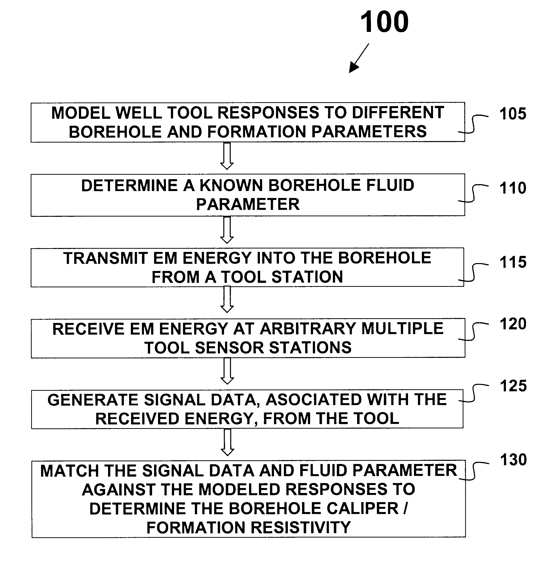
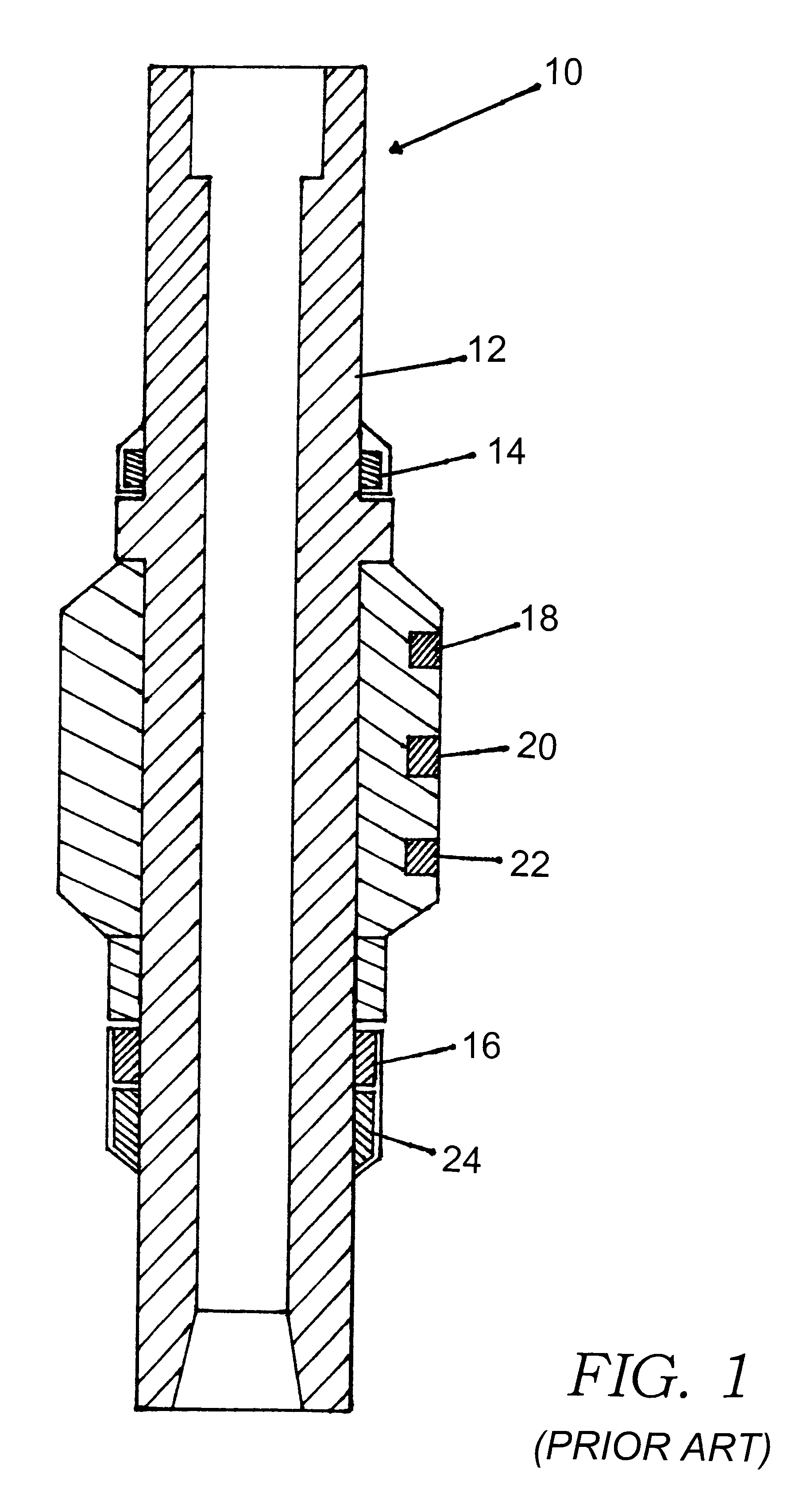
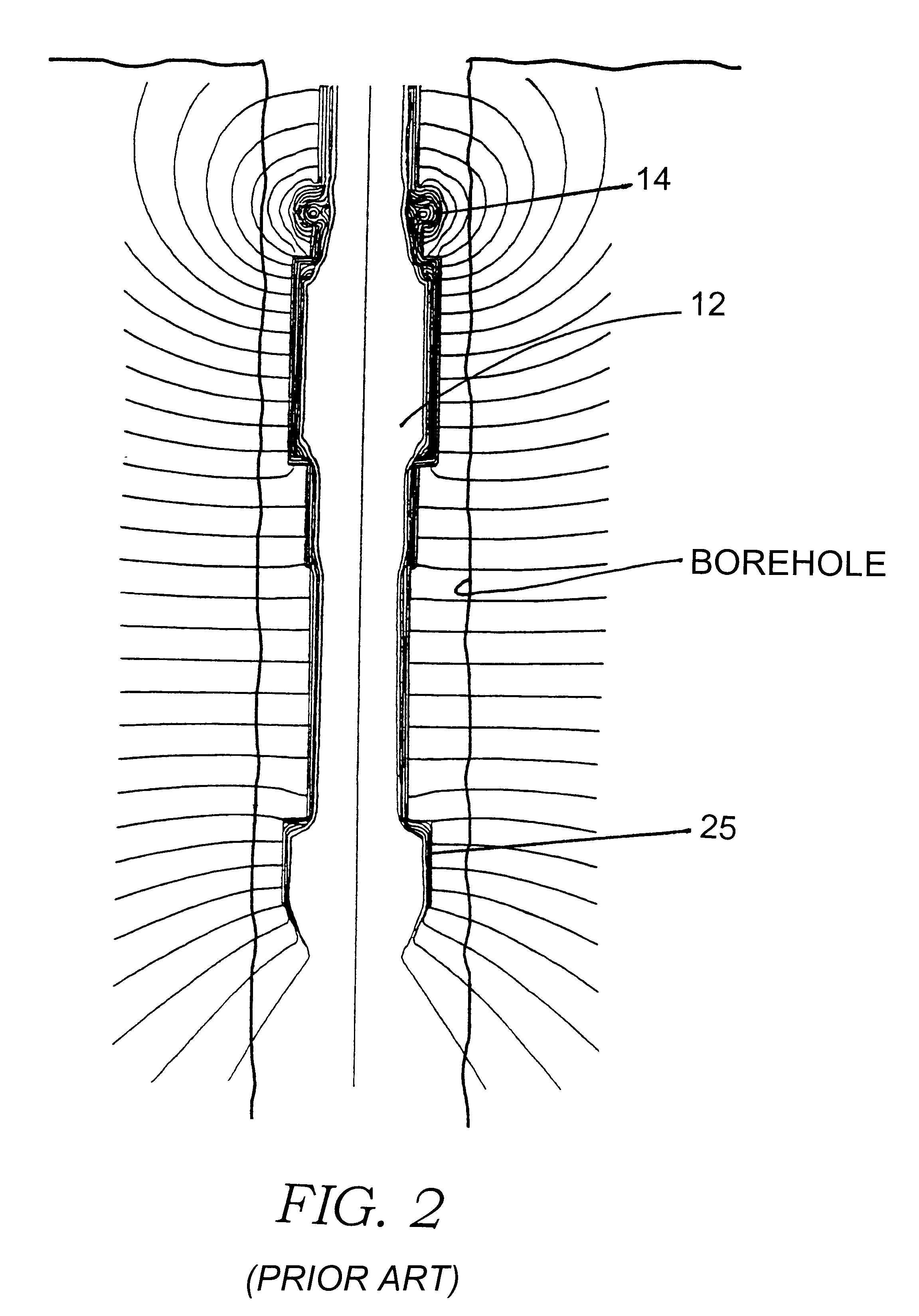
The present invention utilizes EM measurements to calculate a borehole caliper extending to a wide range of diameters and the resistivity of the surrounding formations. U.S. Pat. Nos. 5,235,285, 5,339,036, 5,339,037 and 5,463,320 (all assigned to the assignee of the present invention) disclose embodiments of well tools that can be used to implement the present invention in the manner of operation described in the respective patent. FIG. 1 is representative of such tool embodiments.

As seen in FIG. 1, one embodiment of the tool 10 includes a section of tubular drill collar 12 having mounted thereon a transmitter antenna 14, a receiving ...


PUM


Abstract

A method and apparatus for determining the size or diameter of boreholes extending to a wide range of dimensions and / or the resistivity of the surrounding earth formations utilizing a well tool disposed in the borehole. The method involves generating model data representative of the well tool responses to different borehole diameters contrasted with formation and borehole fluid resistivity values, determining the borehole fluid resistivity, transmitting electromagnetic energy into the formation, measuring the energy shed back into the borehole at arbitrary sensor stations on the tool and generating resistivity signal data associated with the measured energy, and matching the signal data and the fluid resistivity against the modeled response data to determine the borehole caliper and / or formation resistivity. The apparatus forms part of a system for calculating a borehole caliper and / or the surrounding formation resistivity. The apparatus being coupled to a multi-sensor well tool and adapted to respond to signal data generated by the tool. The apparatus further adapted to receive the signal data; to receive a borehole fluid parameter; to store modeled well tool response data; and to process the signal data, the fluid parameter, and the modeled data to determine the borehole caliper and / or formation resistivity.

Description

1. Field of the InventionThis invention relates generally to a method and apparatus for measuring a borehole and the surrounding earth formations and, more particularly, to a technique for calculating the diameter of a borehole and the formation resistivity from electromagnetic ("EM") measurements obtained with a well tool. The invention has general application in the well logging art, but is particularly useful in measuring-while-drilling.2. Description of Related ArtIn order to improve oil and gas drilling and production operations, it is necessary to gather as much information as possible on the properties of the underground earth formation as well the environment in which drilling takes place. Such properties include characteristics of the earth formations traversed by a well borehole, in addition to data on the size and configuration of the borehole itself. Among the characteristics of the earth formation of interest to drillers and petrophysicists is the resistivity of the roc...

Claims


Application Information

Patent Timeline
Patent Type & Authority Patents(United States)
IPC IPC(8): G01V3/30G01V3/18
CPCE21B47/082G01V3/30E21B47/085
Inventor LI, QIMING
Owner SCHLUMBERGER TECH CORP
Why Eureka
Try Eureka