
Phase locked loop control via inner and outer feedback control circuits

a feedback control circuit and phase lock technology, applied in the direction of pulse automatic control, electrical equipment, etc., can solve the problems of relatively slow control circuit having a relatively low limit frequency, jitter in input frequency signal attenuation, and not ideal oscillator practi

Inactive Publication Date: 2002-05-07
TELEFON AB LM ERICSSON (PUBL)
View PDF11 Cites 221 Cited by
  • Summary
  • Abstract
  • Description
  • Claims
  • Application Information

AI Technical Summary

Benefits of technology

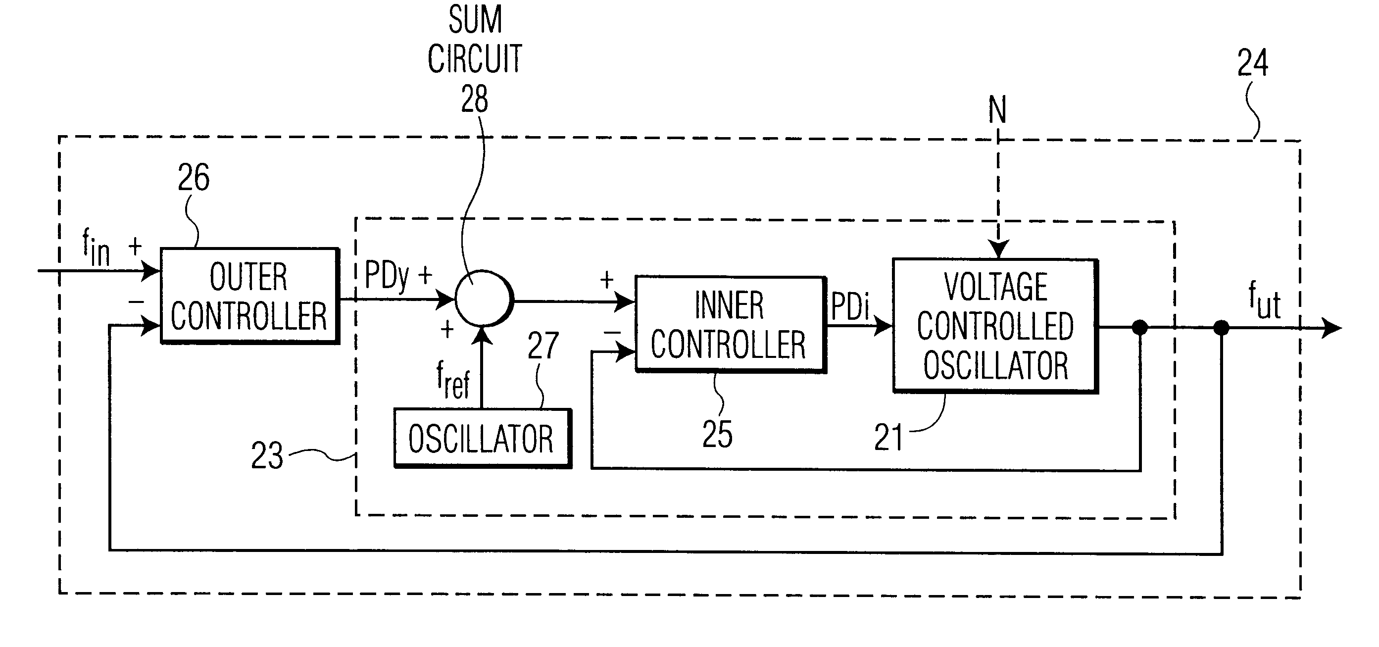
The advantage of the invention is that noise in the voltage-controlled oscillator is removed at the same time as the input frequency is followed and that jitter in the input frequency is attenuated. Other advantages are good frequency and phase stability and that a large working range is obtained and that a low limit frequency (cut off frequency, modulation band width) can be used for attenuating the jitter in the input frequency.
In one embodiment phase meters are used for calculating phase differences, despite that the voltage controlled oscillator primarily controls the frequency. The problem with this is that it becomes necessary to consider both phase and frequency simultaneously. The embodiment relies on the understanding that a phase difference can be seen as an integration of frequency difference and thus either a differentiation or an integration must be provided at suitable locations. According to the embodiment an additional integration is provided in the outer control circuit making the outer control circuit generate an outer output signal consisting of a phase ramp. The advantage of this embodiment is that a simple useful circuit without unnecessary elements is obtained.
In one embodiment the location of an addition and a subtraction according to A+(B-C)=(A+B)-C is interchanged in the implementation. The advantage of this embodiment is that a simple circuit without any unnecessary elements is obtained.

Problems solved by technology

However, such an oscillator is not in practice ideal since the output frequency can be affected by, for example, the supply voltage, temperature, aging of components, humidity and atmospheric pressure.
The first problem is that normally it is not desired that the output frequency follows the input frequency exactly, jitter in the input frequency signal should be attenuated.
This requires a relatively slow control circuit having a relatively low limit frequency.
The other problem is that a voltage controlled oscillator is affected by for example supply voltage, temperature, aging of components, humidity and atmospheric pressure.
None of the documents described in the state of the art has been able to identify these two contradictory problems and has not been able to solve them.
The problem with this is that it becomes necessary to consider both phase and frequency simultaneously.

Method used


Image

  • Phase locked loop control via inner and outer feedback control circuits
  • Phase locked loop control via inner and outer feedback control circuits
  • Phase locked loop control via inner and outer feedback control circuits

Examples


Embodiment Construction

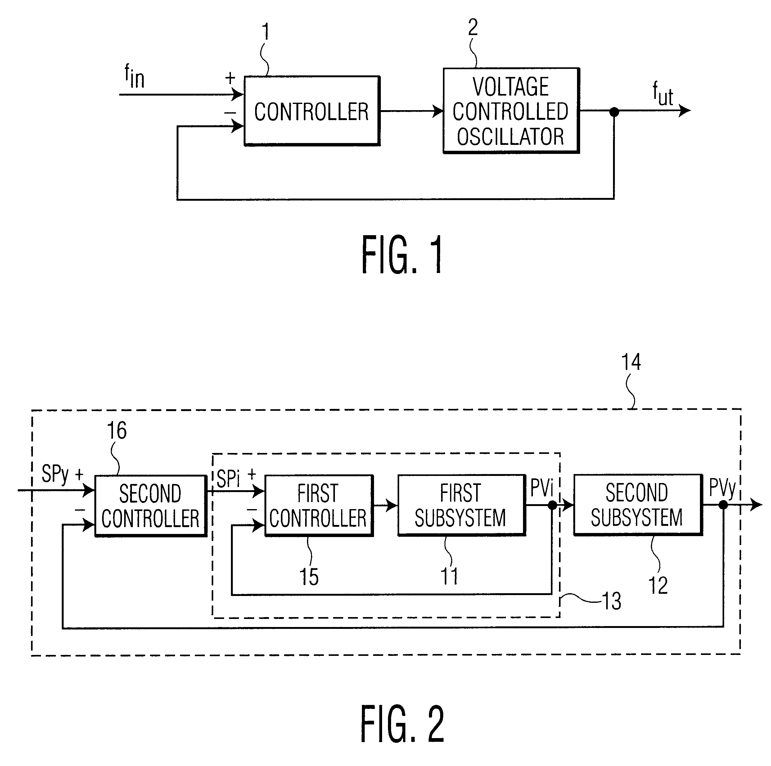
A voltage-controlled oscillator (VCO) is an oscillator having an output frequency which can be controlled by a reference voltage. A voltage controlled oscillator is however rarely ideal and in order to be sure of the obtained output frequency it is suitable to let the oscillator be part of some type of feedback circuit. What this could look like is briefly shown in FIG. 1.

A controller 1 receives an input frequency f.sub.in which is to be followed, and an output frequency f.sub.ut from a voltage controlled oscillator 2. In response to the difference between the input frequency f.sub.in and output frequency f.sub.ut the controller 1 generates an output signal which controls the oscillator 2 towards the input frequency f.sub.in.

The interferences which may affect the oscillator 2 can for example be variations in temperature and supply voltage. It is desirable that these interferences are eliminated as quickly as possible. The control circuit 1 should therefore be fast.

On the other hand ...


PUM


Abstract

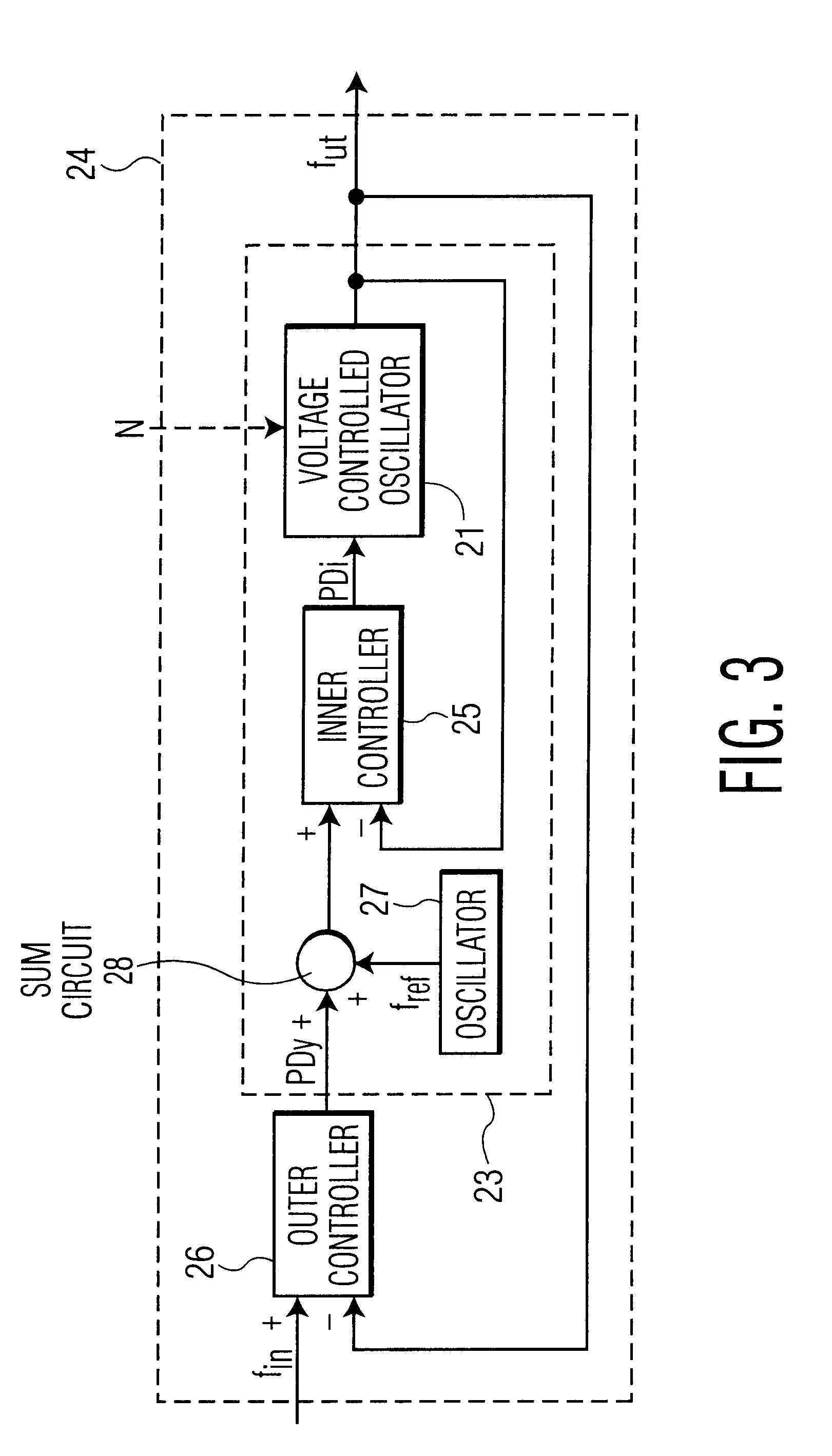
A phase locked loop includes at least one control circuit, where a voltage-controlled oscillator provides an output frequency which is arranged to strive to follow an input frequency. The phase locked loop also includes an outer, slow, negative feedback control circuit, having the input frequency as a setpoint, the output frequency as a process value and an outer output signal. The phase locked loop also includes an inner, fast, negative feedback control circuit, having the sum of a reference frequency from a stable oscillator and the outer output signal as a setpoint, the output frequency as the process value and an inner output signal for controlling the voltage controlled oscillator.

Description

The present invention is related to control of a voltage-controlled oscillator, preferably in a phase locked loop.STATE OF THE ARTPhase Locked Loops (PLL) are used, e.g. for obtaining an output clock frequency which follows an input clock frequency.A phase locked loop can for example comprise a voltage-controlled oscillator (VCO), which generates a frequency depending on an input voltage. However, such an oscillator is not in practice ideal since the output frequency can be affected by, for example, the supply voltage, temperature, aging of components, humidity and atmospheric pressure. Therefore, the oscillator should be comprised in some type of control circuit. A number of different control circuits are possible.In the U.S. patent U.S. Pat. No. 4,787,097, a phase locked loop having a feed back control circuit is shown.In the U.S. patent U.S. Pat. No. 5,463,351, a phase locked loop having two parallel feed back control circuits, where either the first or the second of the control ...

Claims


Application Information

Patent Timeline
IPC IPC(8): H03L7/087H03L7/08
CPCH03L7/087
Inventor WILHELMSSON, MATSM.ANG.RTENSSON, ROLF
Owner TELEFON AB LM ERICSSON (PUBL)
Learn More