Coding system and method for partial response channels

a coding system and partial response technology, applied in the field of partial response channels, can solve the problems of increasing the likelihood of introducing errors, reducing the cost of a blank recordable cd media, and competing interests

Inactive Publication Date: 2002-05-07
AVAGO TECH WIRELESS IP SINGAPORE PTE
View PDF11 Cites 32 Cited by
  • Summary
  • Abstract
  • Description
  • Claims
  • Application Information

AI Technical Summary

Problems solved by technology

The cost of a blank recordable CD media has fallen dramatically.
However, these interests are often competing.
For example, as data densities and access speeds increase, the likelihood of introducing errors also increases.
However, as densities and readback speeds increase, inter-symbol interference arises and the peak detection channel can not provide reliable data detection.
Inter-symbol interference results from the overlap of signal peaks as they stream past the read head at higher and higher rates.
The problem as been that the encoding requires more than one symbol per bit, negatively impacting both disk capacity and drive performance.
The phrase "Partial Response" refers to the fact that PRML does not directly provide user output information.

Method used


Image

  • Coding system and method for partial response channels
  • Coding system and method for partial response channels
  • Coding system and method for partial response channels

Examples


Embodiment Construction

-ary data with varying intensity

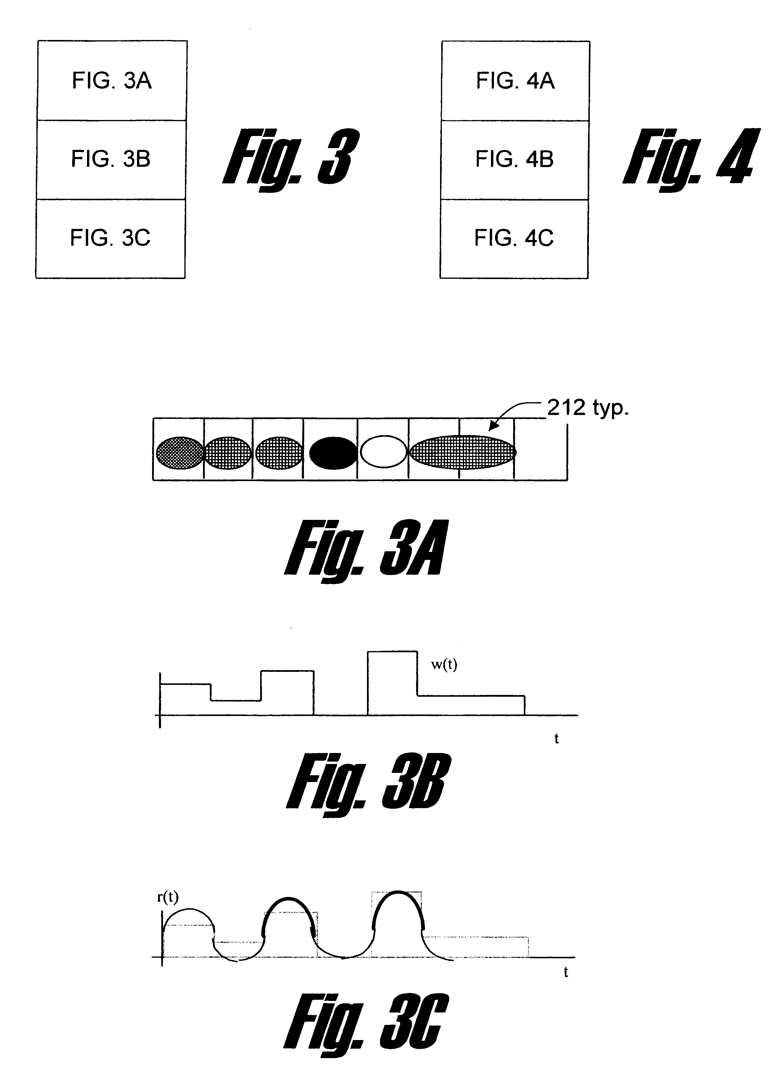
FIG. 3, which comprises FIGS. 3A, 3B and 3C, is a diagram illustrating a multilevel phase change recording system according to one embodiment of the invention. In this example system, the level of each symbol is represented by a different amplitude / phase write signal. Marks written using this write strategy can produce multilevel reflectivities. FIG. 3A shows an example pattern of marks representing the multi-level symbols. In the illustration, various shades of grey are used to illustrate different levels of the M-ary data.

The signal w(t) illustrated in FIG. 3B is a conceptual waveform that represents the example signal written on the disc(or to the channel) as illustrated in FIG. 3A. More specifically, w(t) is the encoded data that is desired to be stored on the disk. In one embodiment, the signal w(t) is applied to modulate the write laser, which, using the proper modulation techniques, can produce the reflectivities as illustrated in FIG. 3A.

FIG. ...


PUM


Abstract

A system and method for reading data to and writing data from multi-level (M-ary) partial response channels uses a trellis coder to encode an input bit stream sequence into a stream of multi-level data symbols. The data symbols are written to the partial response channel using any of a number of techniques. Preferably, the trellis coder anticipates the modulation transfer function of the partial response channel in encoding the data. Because the partial response channel has its own transfer function, the relationship between the data read from the channel and the actual input data bits is a function not only of the data encoder but also of the partial response channel. Therefore, a decoder specification used to implement the decoder takes into account the effect of the trellis encoder as well as the effect of the partial response channel.

Description

1. Field of the InventionThe present invention relates generally to partial response channels, and more particularly to a system and method for equalization and coding on a partial response channel.2. Related ArtThe proliferation of processors and processor-based systems in recent years has led to a tremendous increase in the ability of businesses, industry and individuals to share or otherwise communicate information. Most computers and workstations in today's homes and offices are connected in some manner to another computer or workstation, either locally or remotely. An early form of such inter-connection of computing systems is the local area network (LAN). Using LAN technology, several computers, workstations, peripherals, or other related devices can be connected to share data among one another and to share network resources.Another technique used for sharing data among a plurality of computing resources is by writing the data to a data storage medium, and physically transport...

Claims


Application Information

Patent Timeline
Patent Type & Authority Patents(United States)
IPC IPC(8): H04L25/497H04L1/00
CPCH04L25/497H04L1/0059G11B20/1496G11B20/1488
Inventor MCLAUGHLIN, STEVEN W.LEE, DAVID C.ZINGMAN, JONATHAN A.FAN, JOHN L.
Owner AVAGO TECH WIRELESS IP SINGAPORE PTE
Why Eureka
Try Eureka