Sensor and detection system having wide diverging beam optics

Inactive Publication Date: 2002-05-21
CYBEROPTICS SEMICON
View PDF22 Cites 7 Cited by
  • Summary
  • Abstract
  • Description
  • Claims
  • Application Information

AI Technical Summary

Benefits of technology

Accordingly, it is an object of the present invention to provide a sensor and detection system with improved angle of coverage.
FIG. 6 is a partially cut away top plan view of the sensor according to a second embodiment of the present invention and shows how the sensor of the present invention may detect an object that is present at an angle of incidence that deviates significantly from position which would generate ideal reflection to the receiver.

Problems solved by technology

In particular it has been found to be difficult to detect the edge of objects, or objects with small, specular surfaces.
This results in a "blind spot" where the light is not detected.

Method used


Image

  • Sensor and detection system having wide diverging beam optics
  • Sensor and detection system having wide diverging beam optics
  • Sensor and detection system having wide diverging beam optics

Examples


Embodiment Construction

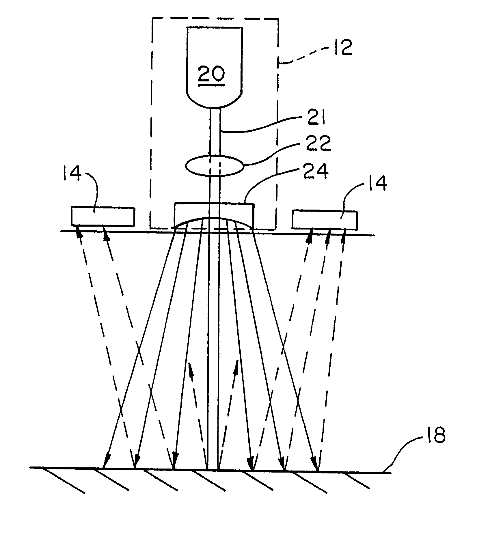
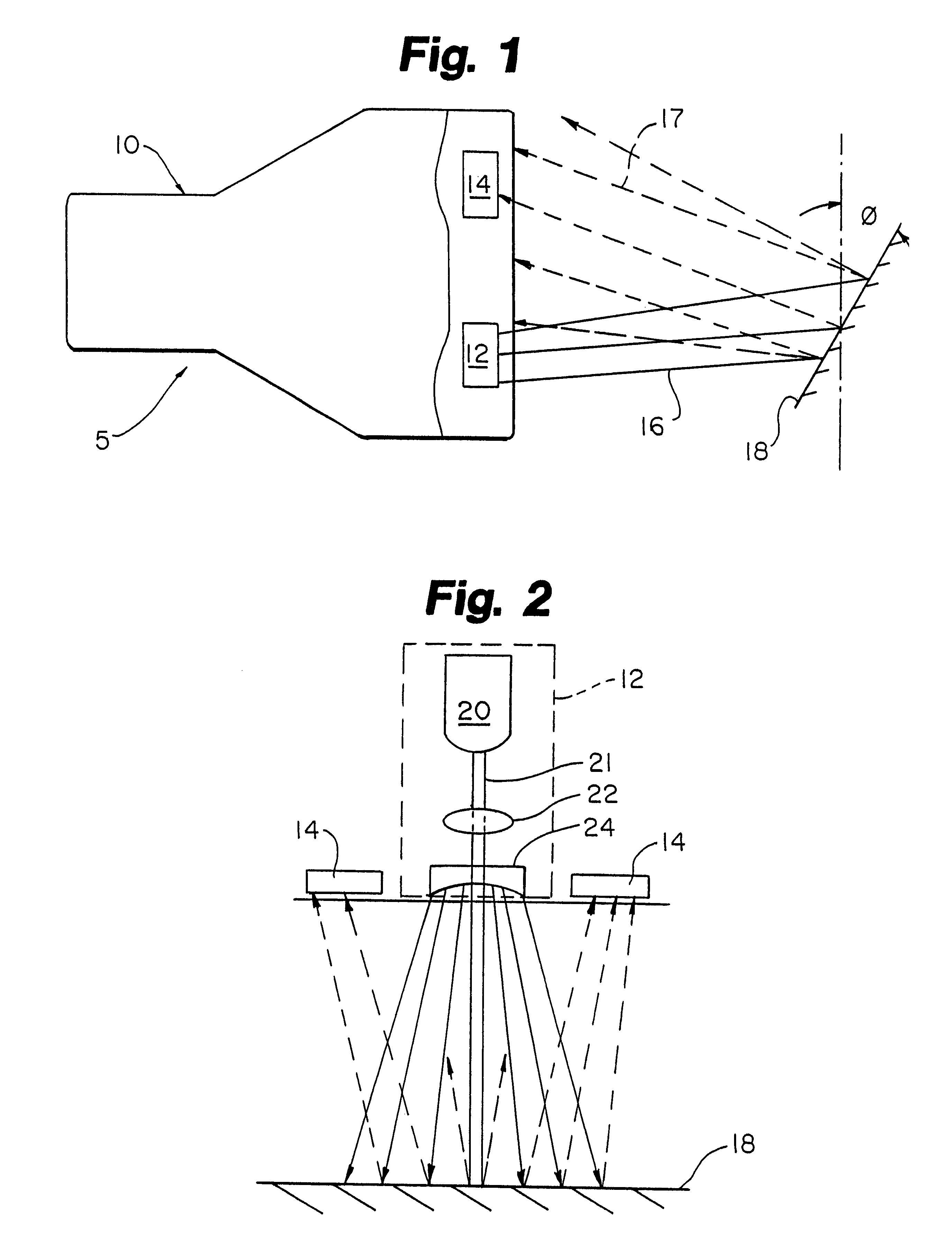
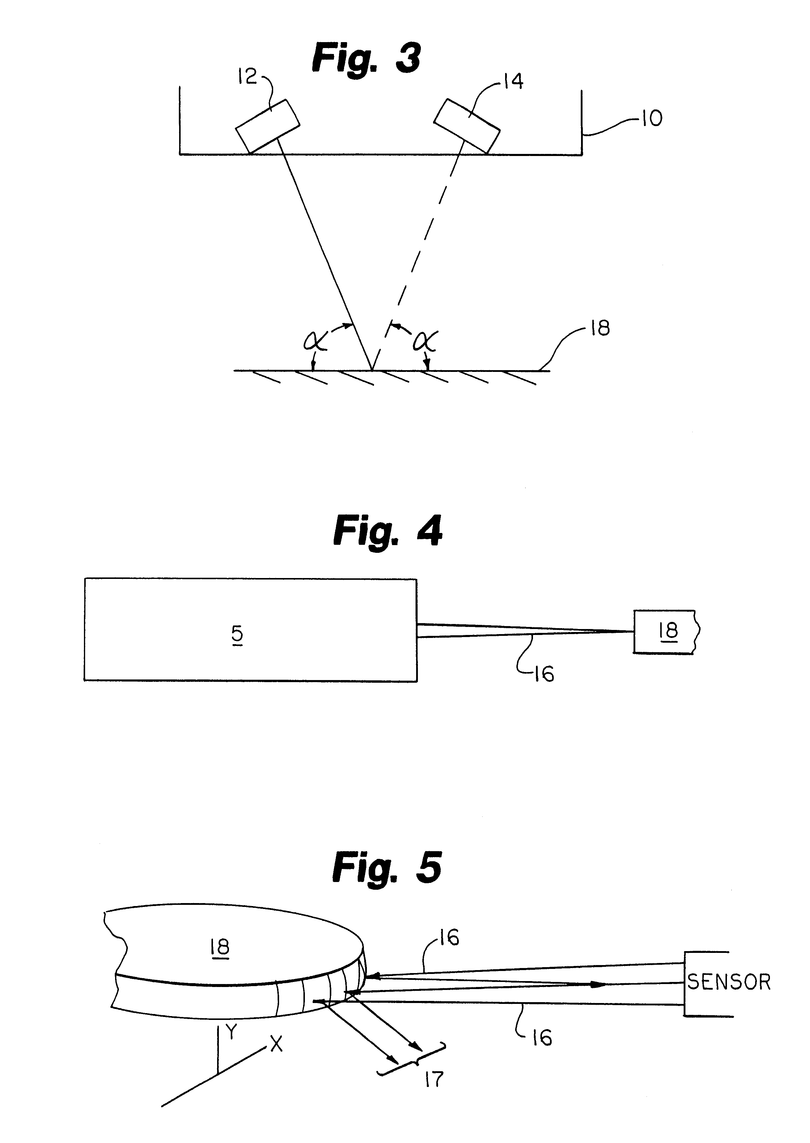
Turning to the drawings, wherein like components are designated by like reference numerals, FIGS. 1 and 2 are two views of the sensor and detection system of the present invention. FIG. 1 shows a sensor 5 comprising a housing 10 and wherein the housing 10 contains at least one transmitter 12 and at least one receiver 14. The transmitter 12 and receiver 14 are spaced apart from each other, and are mounted on a printed circuit board (not shown) within the sensor housing 10.

The transmitter 12 emits light 16 which is directed towards the object 18 to be detected. The light is reflected off the object 18 back towards the receiver 14. The receiver 14 is a light detector and is spaced apart from the transmitter for receiving the reflected light 17. It is important to note that a plurality of receivers and transmitters may be used, however, the present invention is also capable of increasing the range of accurate detection and measurement using just one transmitter and receiver pair. Also, ...


PUM


Abstract

A sensor and detection system is included. The sensor includes at least one transmitter which has associated optical elements for emitting at least one light beam toward the object to be detected. At least one receiver is positioned adjacent the transmitter for receiving light reflected from an edge of the object. The receiver generates a signal responsive to the reflected light. The associated optical elements of the transmitter include a converging lens for emitting a focused light beam in one plane, and a cylindrical lens for emitting a diverging light beam in another plane, such that a portion of the reflected light is diverging and is received by the receiver over a wide angle of coverage.

Description

The present invention relates generally to a sensor and detection system for detecting the presence or position of surfaces, and more particularly to a sensor and detection system having wide diverging beam optics for increasing the angle of detection coverage.Sensors are used for a variety of purposes. One useful purpose is as an detection system for detecting the presence of objects. In particular it has been found to be difficult to detect the edge of objects, or objects with small, specular surfaces. A sensor and detection system and method which solves this problem is taught in U.S. Pat. No. 5,504,345, which is owned by assignee, and is herein incorporated by reference. The '345 patent discloses a semiconductor wafer and magnetic disk edge detection system having converging dual-beam optical sensor. The sensor comprises at least two light sources, and at least two light detectors. The light sources, or the light beams emanating form the sources, are spatially oriented such that...

Claims


Application Information

Patent Timeline
IPC IPC(8): G01B11/24G01B11/25G01V8/12G01J1/02G01J1/06
CPCG01B11/25Y10S414/136
Inventor CERNY, MARKBARTUNEK, HANS
Owner CYBEROPTICS SEMICON
Why Eureka
Try Eureka