
Optical connector

A technology for connectors and mating connectors, which is applied in the direction of instruments, optics, light guides, etc., can solve the problems of increasing light loss, and achieve the effects of improving anti-fouling, loose mechanical precision requirements, and low light loss

Active Publication Date: 2015-07-15
3M INNOVATIVE PROPERTIES CO
View PDF5 Cites 6 Cited by
  • Summary
  • Abstract
  • Description
  • Claims
  • Application Information

AI Technical Summary

Problems solved by technology

For each of these contact methods, a small amount of dust at the end of the mated fiber can greatly increase light loss

Method used


Image

  • Optical connector
  • Optical connector
  • Optical connector

Examples


Embodiment Construction

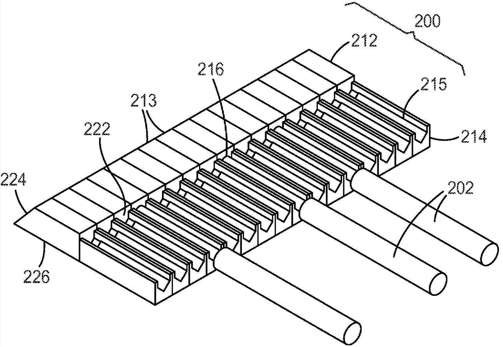
[0023] Fiber optic ribbons are used in fiber optic cables used in many applications. These ribbons consist of a set of coated optical fibers bonded together into a line (typically 4, 8 or 12 fibers in a line). Individual glass optical fibers together with their protective coatings are typically 250 microns in diameter, while fiber-optic ribbons typically have a fiber-to-fiber pitch of 250 microns. This 250-micron pitch has also been used in optical transceivers with a variety of designs, with the active optics spaced by the same 250-micron pitch.

[0024] Currently available expanded beam multi-fiber connectors typically limit the beam diameter to 250 microns to match the ribbon spacing. To achieve beam diameters larger than the fiber pitch, current connectors typically require the fiber ribbon to be separated into individual fibers by hand before the fiber is mounted on the connector.

[0025] Generally, a single fiber optic connector includes a precision cylindrical ferrul...


PUM


Abstract

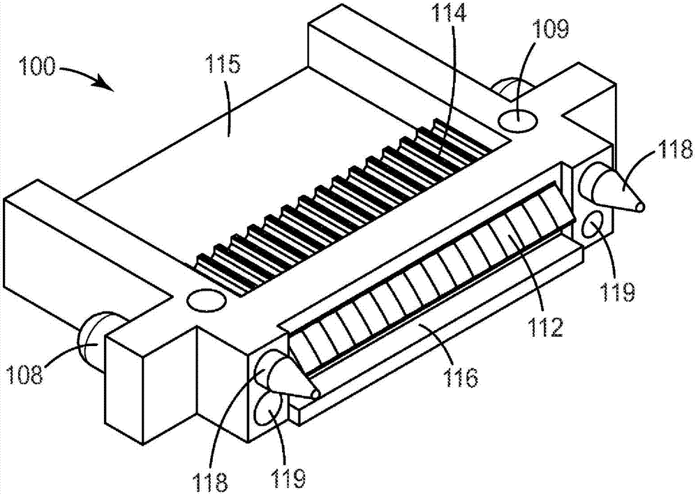
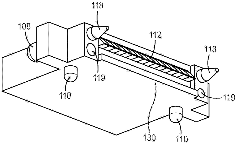
Optical connectors are provided for connecting sets of optical waveguides, such as optical fiber ribbons to each other, to printed circuit boards, or to backplanes. The provided connectors utilize expanded beam optics with non-contact optical mating resulting in relaxed mechanical precision requirements. The provided connectors can have low optical loss, are easily scalable to high channel count (optical fibers per connector) and can be compatible with low insertion force blind mating.

Description

[0001] Related applications [0002] This application is related to commonly owned patent applications: Attorney Docket No. 70228US002, titled "Optical Connector," and Attorney Docket No. 71021US002, titled "Unitary Optical Ferrule," which Both applications were filed on the same date as this application and are hereby incorporated by reference in their entirety. technical field [0003] The present disclosure relates to optical connectors for connecting sets of optical waveguides, such as optical fiber ribbons. Background technique [0004] Fiber optic connectors are used to connect optical fibers in a variety of applications including: telecommunications networks, local area networks, data center links, and interconnects in high-performance computers. These connectors can be grouped into single-fiber and multi-fiber designs, and can also be grouped by contact type. Common contacting methods include: physical contacting, in which the mating fiber ends are polished to a c...

Claims


Application Information

Patent Timeline
IPC IPC(8): G02B6/36G02B6/38G02B6/42
CPCG02B6/3885G02B6/3829G02B6/4214G02B6/3652G02B6/3676G02B6/3839G02B6/43G02B6/383G02B6/3853G02B6/3845G02B6/3883
Inventor M·A·哈泽T·L·史密斯B·J·科克王丁A·R·马修斯
Owner 3M INNOVATIVE PROPERTIES CO
Learn More