
Method of inspecting pattern and inspecting instrument

a micro-miniature pattern and inspection instrument technology, applied in the direction of instruments, semiconductor/solid-state device testing/measurement, image enhancement, etc., to achieve the effect of high-accuracy inspection, easy setting of review conditions, and long tim

Inactive Publication Date: 2006-09-26
HITACHI TOKYO ELECTRONICS
View PDF20 Cites 7 Cited by
  • Summary
  • Abstract
  • Description
  • Claims
  • Application Information

AI Technical Summary

Benefits of technology

[0019]It is a first object of the present invention to provide a pattern inspecting instrument and a method of inspecting pattern for inspecting a fine pattern such as a circuit on the substrate surface of semiconductor device or the like by radiating thereto a white beam, laser beam or electron beam in order to efficiently inspect, review and discriminate, within a short period, various particles and defects such as the detected surface roughness, defect of figures and particles and moreover electrical defects.
[0020]Moreover, it is a second object of the present invention to provide a pattern inspecting instrument and a method of inspecting pattern for realizing high-speed and highly accurate review and classification of various particles and defects explained above.
[0021]Moreover, it is a third object of the present invention to provide an inspection instrument and an inspection method that assure, through application to various kinds of semiconductor devices in multiple steps and the other fine circuit patterns in the earlier stage, highly efficient detection of process defect of semiconductor device or the like, reflection of the result on the manufacturing conditions, enhancement of reliability of semiconductor device and reduction of failure rate.

Problems solved by technology

However, such inspection instrument provides the positional information generated by a defect and the size of defect.

Method used


Image

  • Method of inspecting pattern and inspecting instrument
  • Method of inspecting pattern and inspecting instrument
  • Method of inspecting pattern and inspecting instrument

Examples


Embodiment Construction

[0052]The pattern inspection system and the method of inspecting pattern of the present invention will be explained in detail with reference to the accompanying drawings.

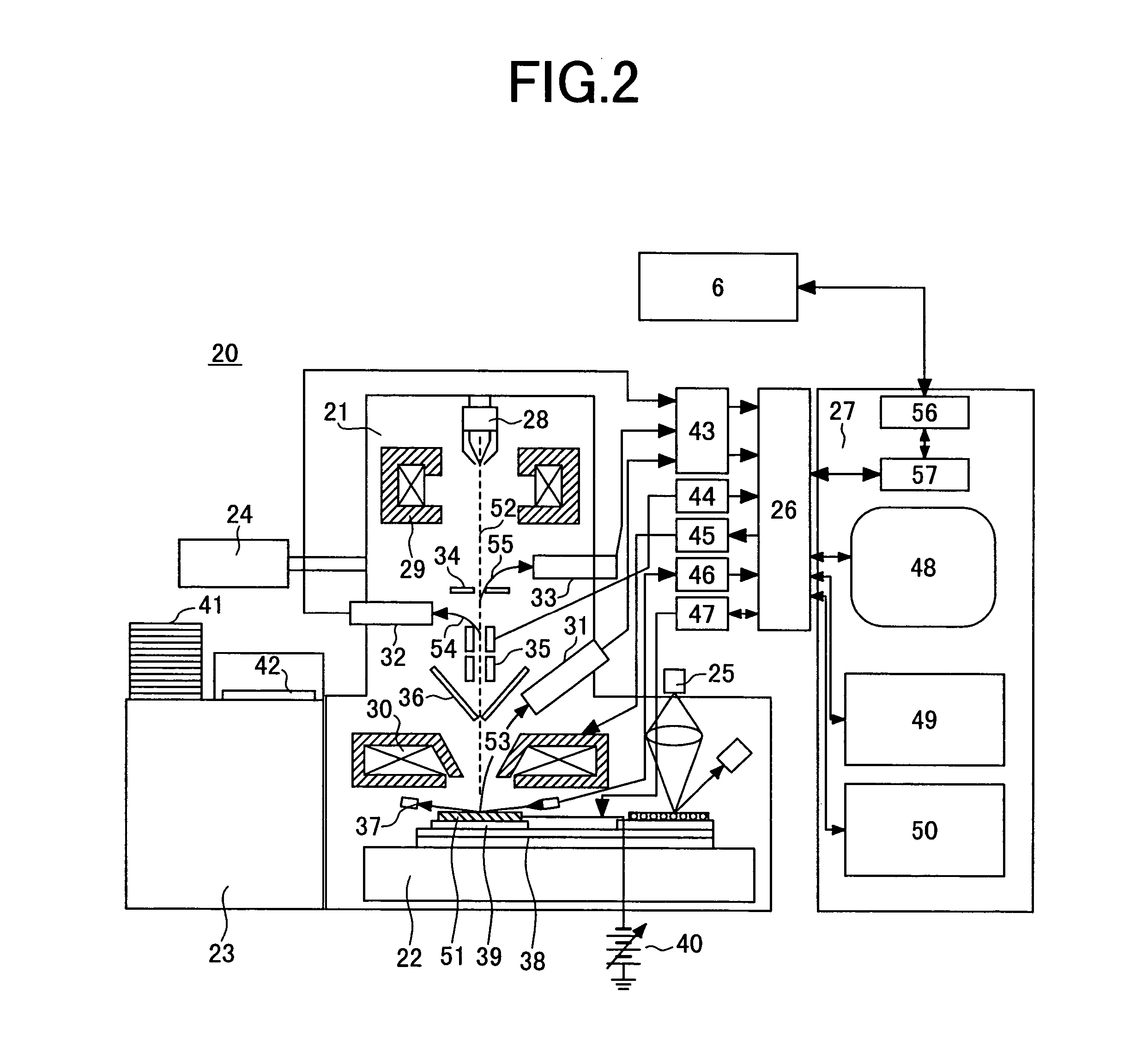
[0053]In this embodiment, an inspection method and an inspection system will be explained to form an image using electron beam in order to detect existence of defect on a circuit pattern from such image and classify the contents of defect for the circuit pattern that is already inspected with the other inspection system. Here, as an example, inspection of a circuit pattern of a semiconductor device formed on a wafer will be explained.

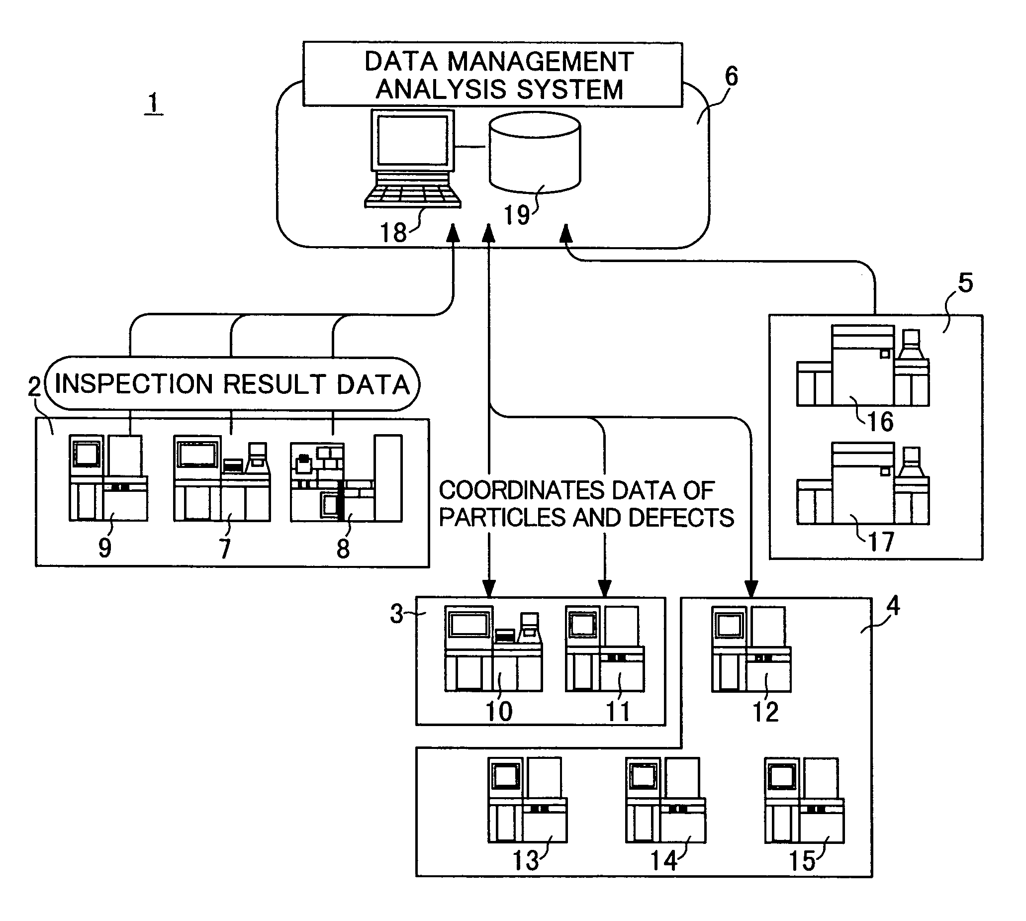
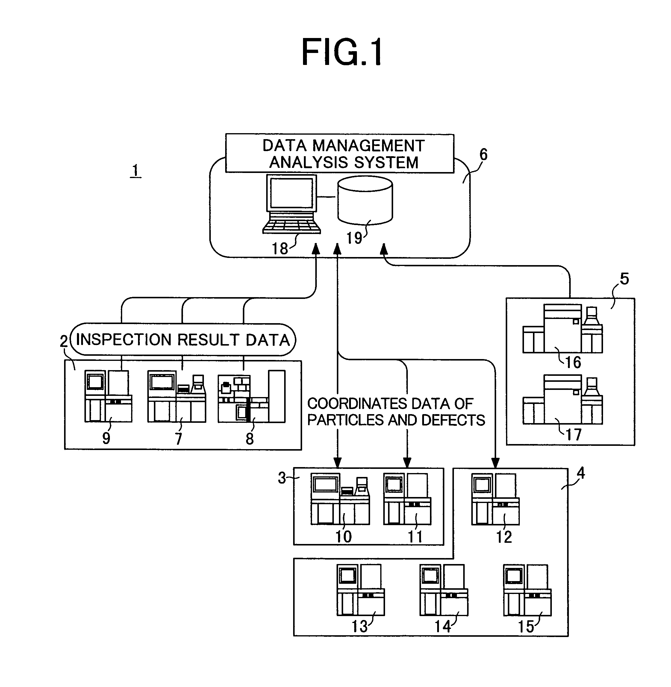
[0054]First, the outline of a pattern inspection system using a pattern inspection system of the present invention is illustrated in FIG. 1. The pattern inline inspection system 1 includes an inspection system 2 for finding out unknown particles and defects, a review system 3 for receiving an information of coordinates or the like of defect found out by the inspection system 2 to output...


PUM

PropertyMeasurementUnit
roughnessaaaaaaaaaa
voltage contrastaaaaaaaaaa
defect inspectingaaaaaaaaaa

Abstract

A sample inspection system having a sample stage holding a sample to be inspected, electron beam optics so as to radiate an electron beam to the sample, a detector unit that detects a secondly generated signal generated in response to radiation of the sample by the electron beam, a storage for storing a plurality of images obtained from the generated signal and information for classifying the plurality of images by a type of defect in the sample, and an image processing unit. The image processing unit retrieves any of the plurality of images and classifies the retrieved image depending on the type of defect including an electrical defect and a defect in the figure.

Description

CROSS REFERENCE TO RELATED APPLICATION[0001]This is a continuation of U.S. application Ser. No. 10 / 463,576, filed Jun. 18, 2003, now U.S. Pat. No. 6,777,677, which is a continuation of U.S. application Ser. No. 09 / 725,900, filed Nov. 30, 2000, now U.S. Pat. No. 6,583,414, the subject matter of which is incorporated by reference herein.BACKGROUND OF THE INVENTION[0002]The present invention relates to a method and an instrument for manufacturing elements including micro-miniature patterns on a substrate and particularly to an inspecting instrument and a method of inspecting micro-miniature patterns such as the circuits or the like in a semiconductor device and a liquid crystal device and more particularly to an inspecting instrument and a method of inspecting patterns on a wafer that is placed in the course of manufacture of semiconductor device and a method of manufacturing a semiconductor device using the same.[0003]A related art will be explained using an example of inspection of a...

Claims


Application Information

Patent Timeline
Patent Type & Authority Patents(United States)
IPC IPC(8): H01J37/00H01J37/256G01Q30/02G01N21/956G01N23/20G01N23/225G01Q30/04G01Q30/20G01R1/06G01R31/302H01L21/027H01L21/66
CPCG01N23/20G06T7/0004H01J2237/2817H01J2237/2487G06T2207/30148
Inventor NOZOE, MARINISHIYAMA, HIDETOSHIHIJIKATA, SHIGEAKIWATANABE, KENJIABE, KOJI
Owner HITACHI TOKYO ELECTRONICS
Learn More