Computer system including core logic unit with internal register for peripheral status

a computer system and register technology, applied in multi-programming arrangements, data conversion, instruments, etc., can solve the problems of large disadvantages of shared interrupt architecture, inability of central processing units to tell, and time-consuming polling process

Inactive Publication Date: 2002-05-21
MICRON TECH INC
View PDF21 Cites 46 Cited by
  • Summary
  • Abstract
  • Description
  • Claims
  • Application Information

AI Technical Summary

Problems solved by technology

However, a shared interrupt architecture suffers from a major disadvantage.
This is because all of the peripheral devices generate the same interrupt signal, and the central processing unit cannot tell from the interrupt signal which peripheral devices require servicing.
This polling process can be quite time-consuming.
Polling reduces CPU efficiency, because the CPU must perform multiple bus transactions to poll the peripheral devices, and each bus transaction can require a large number of CPU cycles in a high performance computing system.
Furthermore, polling increases the time required for servicing an interrupt.
This may create problems for peripheral devices that require servicing in a timely manner.

Method used


Image

  • Computer system including core logic unit with internal register for peripheral status
  • Computer system including core logic unit with internal register for peripheral status
  • Computer system including core logic unit with internal register for peripheral status

Examples


Embodiment Construction

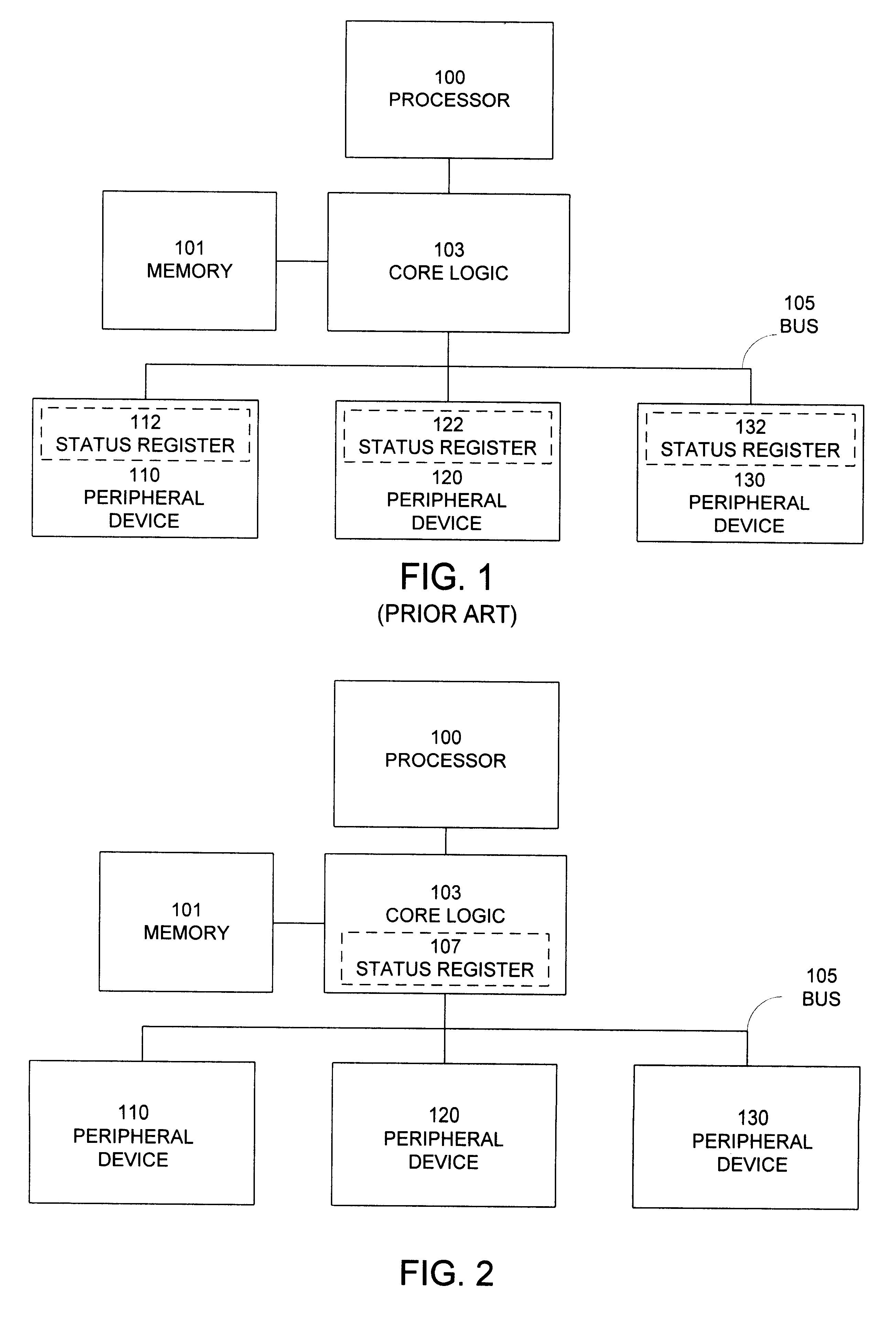
FIG. 1 illustrates a prior art computer system, wherein a processor 100 reads status registers 112, 122 and 132, located at respective peripheral devices 110, 120 and 130. Processor 100 is coupled to memory 101 and bus 105 through core logic unit 103. Processor 100 can access peripheral devices 110, 120 and 130 through bus 105. In response to an interrupt, processor 100 polls status registers 112, 122 and 132 in order to determine which of peripheral devices 110, 120 and 130 require processing. This polling requires multiple operations over bus 105.

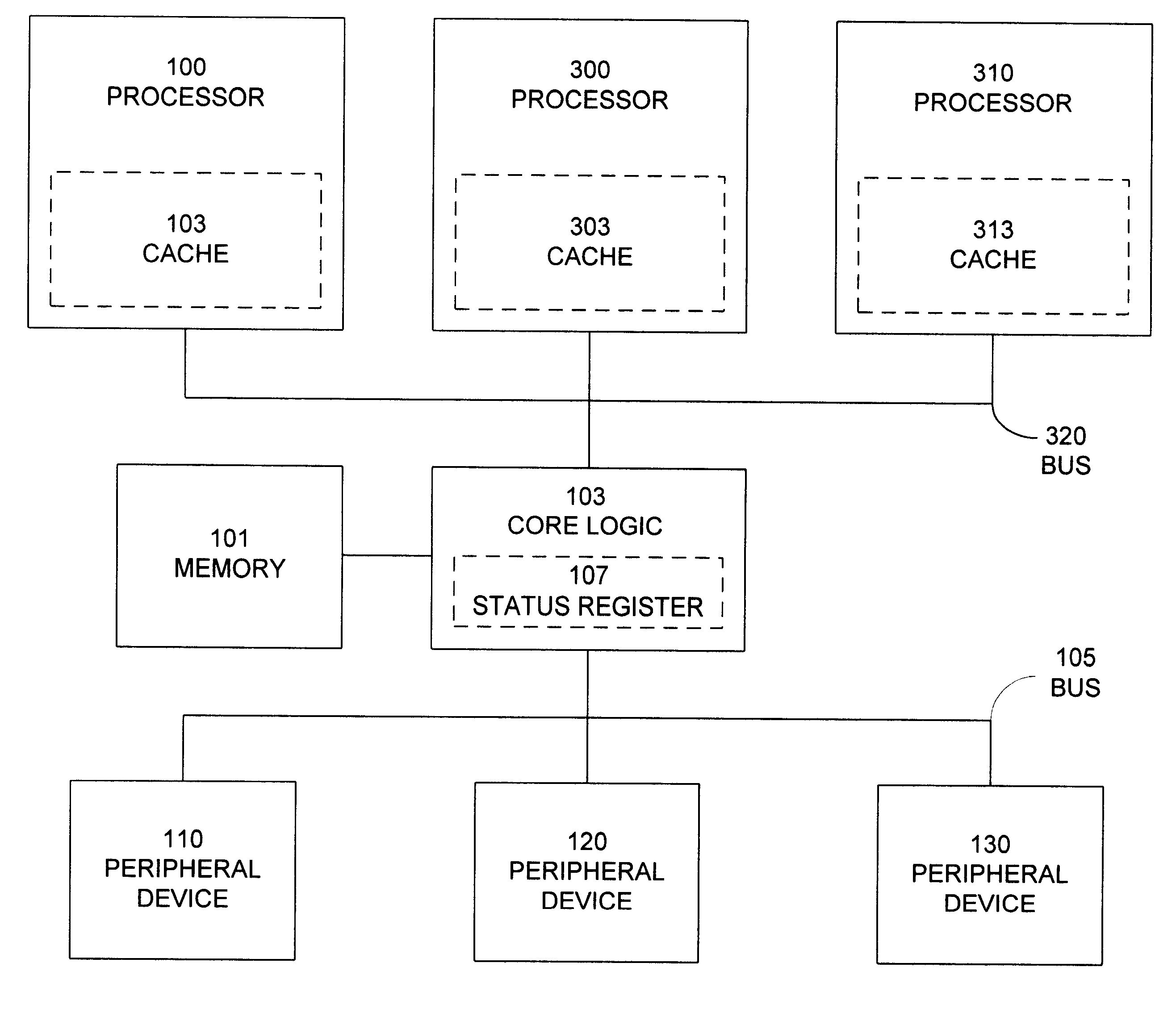
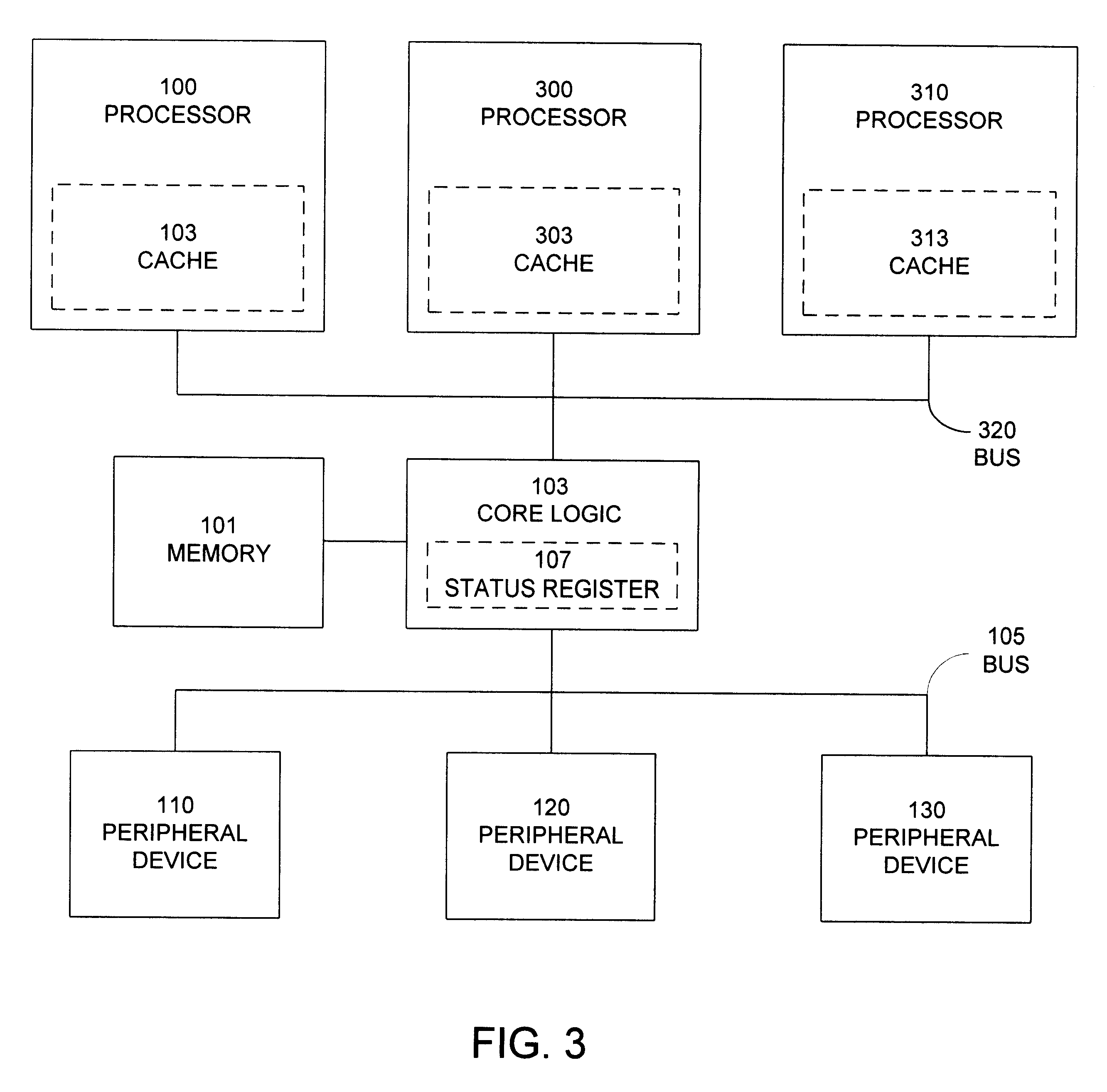
FIG. 2 illustrates a computer system including a processor 100 with a core logic unit 103 with an internal status register 107 for storing the status of peripheral devices in accordance with an embodiment of the present invention. As in the system illustrated in FIG. 1, processor 100 is coupled to memory 101 and bus 105 through core logic unit 103. Processor 100 can access peripheral devices 110, 120 and 130 through bus 105.

However, the e...


PUM


Abstract

One embodiment of the present invention provides a computer system that maintains status information for several peripheral devices in a status register, which is located within a core logic unit in the computer system. In this embodiment, a peripheral device updates the status register if its status changes by performing a bus master operation to transfer status information to the status register. It then generates an interrupt to indicate to a processor that it requires servicing. When the processor services the interrupt, the processor merely has to read the status register to determine which peripheral device requires processing. This is a very fast operation because the status register is internal to the core logic. No time-consuming polling of peripheral devices is required to determine the status of the peripheral devices. Thus, one embodiment of the present invention provides an apparatus within a core logic device that maintains status information for peripheral devices in a status register. This apparatus includes a peripheral communication channel coupled to a number of peripheral devices. An updating circuit is located within the core logic unit and is coupled between the peripheral communication channel and the status register. This updating circuit includes a mechanism to update the status register in response to signals containing status information received from the peripheral devices through the peripheral communication channel.

Description

1. Field of the InventionThe present invention relates to peripheral devices in computer systems, and more particularly to a system with a centralized core logic register for maintaining status information for peripheral devices in a computer system.2. Related ArtComputer systems typically include a central processing unit that is coupled to and communicates with a plurality of peripheral devices, typically through a computer system bus. These peripheral devices can include: data storage devices, such as disk drives and tape drives; data input devices, such as a keyboard or a mouse; data output devices, such as a video display or an audio speaker; and communication devices, such as a network interface controller. A peripheral device frequently requires attention from the central processing unit in order to transfer data between the central processing unit and the peripheral device, or to otherwise command and manipulate the peripheral device. This attention is typically triggered by...

Claims


Application Information

Patent Timeline
Patent Type & Authority Patents(United States)
IPC IPC(8): G06F13/12
CPCG06F13/126
Inventor KLEIN, DEAN A.
Owner MICRON TECH INC
Why Eureka
Try Eureka