Device and method for performing a dehumidifying operation

a technology of dehumidification and equipment, applied in the direction of domestic cooling equipment, lighting and heating equipment, separation processes, etc., can solve the problems of evaporator pressure and dew point strong variation, device premature wear and tear, and conduit and instrument corrosion

Inactive Publication Date: 2002-05-28
ATLAS COPCO AIRPOWER NV
View PDF12 Cites 67 Cited by
  • Summary
  • Abstract
  • Description
  • Claims
  • Application Information

AI Technical Summary

Benefits of technology

Instead of switching the motor on and off, its speed is adapted. By increasing the number of revolutions of the motor, a larger mass flow rate of cooling liquid can be transferred by pumping and therefore a larger cooling capacity can be delivered.
By the combination of the bypass with bypass-closing element and open / closed closing element with speed-controlled compressor, not only the number of times the motor is stopped and restarted is significantly reduced, but a major energy saving is possible. Other advantages thereof will be explained in the following.

Problems solved by technology

Due to the condensation water, corrosion will occur in conduits and instruments and the devices will show a premature wear and tear.
Such regulation, however, is very disadvantageous in consideration of the fact that, with a small load, the compressor is switched on and off continuously, whereas also the evaporator pressure and the dew points strongly vary.
Moreover, the condensation dryer has to be constructed rather large.
In both kinds of devices, the regulation thus is performed by switching the motor on and off, which, especially with a small load, will happen often, which causes considerable wear and tear of the compressor and is disadvantageous.
In consideration of the fact that the compressor motor is working continuously, the energy consumption even with no or low load therefore is equal to the energy consumption with nominal load as the high and low pressure in the cooling circuit are continuously kept constant, thus resulting in a relatively high energy consumption.
However, the motor is driven continuously on full speed, such that energy consumption remains relatively high.

Method used


Image

  • Device and method for performing a dehumidifying operation
  • Device and method for performing a dehumidifying operation
  • Device and method for performing a dehumidifying operation

Examples


Embodiment Construction

.

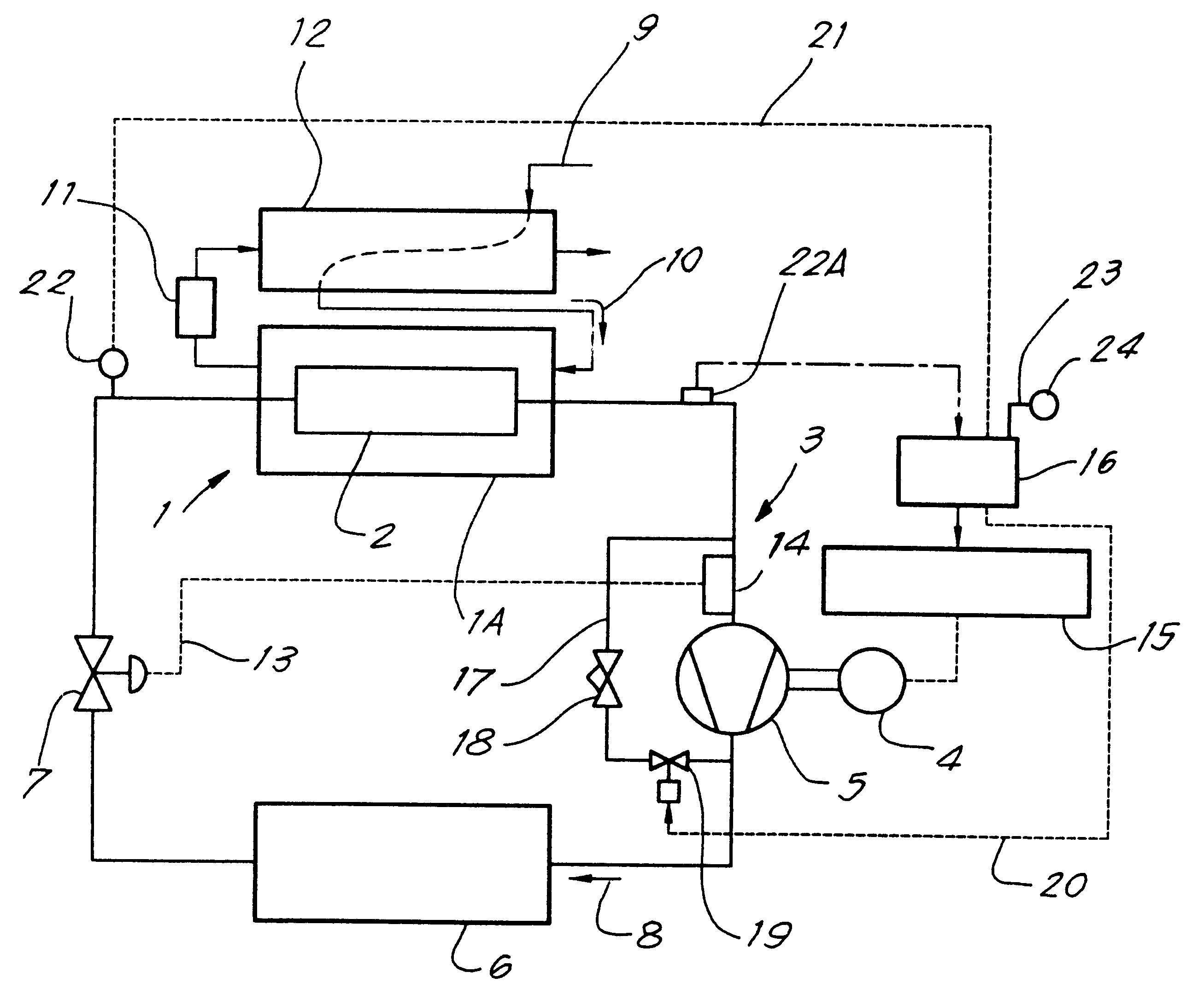
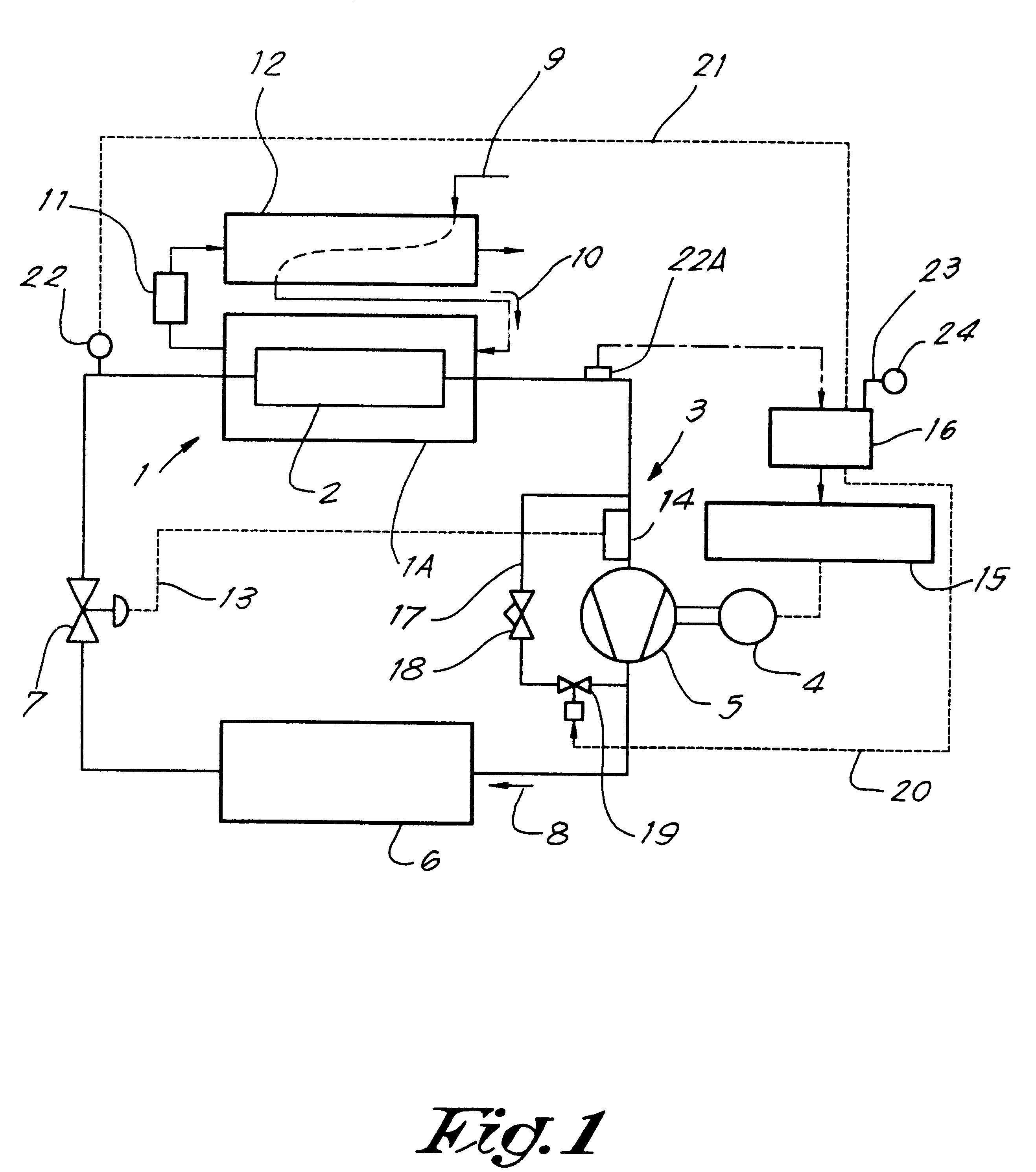
The device for cool-drying which is schematically represented in FIG. 1, substantially comprises a heat exchange 1, the primary part of which forms the evaporator 2 of a cooling circuit 3 in which, successively, also a compressor 5, driven by an electric motor 4, a condenser 6 and an expansion valve 7 are disposed.

This cooling circuit 3 is filled with a cooling medium or fluid, for example, Freon 404a, the flow direction of which is represented by arrow 8.

The secondary part 1A of the heat exchanger 1 forms part of the conduit 9 for humid air to be dried, the flow direction of which is indicated by arrow 10.

After the heat exchanger 1 and, thus, at its outlet, a liquid separator 11 is disposed in conduit 9.

Possibly, said conduit 9, before reaching the heat exchanger 1, may extend with a portion through a pre-cooler or recuperative heat exchanger 12 and subsequently, downstream of liquid separator 11, again extend through the recuperative heat exchanger 12, in reverse flow direction t...


PUM

PropertyMeasurementUnit
temperatureaaaaaaaaaa
evaporation pressureaaaaaaaaaa

Abstract

The invention relates to a device for cool-drying, comprising a heat exchanger (1), the primary part of which is the evaporator (2) of a cooling circuit (3) which further comprises a compressor (5) driven by an electric motor (4) being bridged-over by means of a bypass (17) with therein a bypass-closing element (18) and an open / closed closing element (19). The secondary part (1A) of the heat exchanger (1) forms part of a conduit (9) for the gas and, at the outlet of this heat exchanger (1), a liquid separator (11) is disposed. The device comprises means (15) for regulating the speed of the motor (4), which means are controlled by means of a control device (16) in function of the value measured by the measuring means (22, 22A).

Description

A) Field of the InventionThis invention relates to a device for dehumidifying by cool-drying a gas and comprises a heat exchanger, the primary part of which is the evaporator of a cooling circuit which further comprises a compressor driven by an electric motor, a condensor, an expansion means between the outlet of the condenser and the inlet of the evaporator, a control device for controlling said motor and measuring means coupled thereto, whereby the compressor is bridged-over by a bypass with therein a bypass-closing element or valve and an open / closed valve or element, whereas the secondary part of the heat exchanger forms part of a conduit for the gas and whereby, at the outlet of said heat exchanger, a liquid separator is disposed in said conduit.Amongst others, such devices are used for drying compressed air.B) Discussion of the Related ArtCompressed air delivered by a compressor in most cases is saturated with water vapour or, in other words, has a relative humidity of 100%. ...

Claims


Application Information

Patent Timeline
Patent Type & Authority Patents(United States)
IPC IPC(8): B01D5/00B01D53/26F25B49/02F25B1/00F26B21/00
CPCB01D5/0039B01D53/265F25B49/025F25B2400/0401F25B2700/21174F25B2600/021F25B2700/197F25B2700/21173F25B2400/0403F25B1/00
Inventor VANDERSTRAETEN, BART ETIENNE AGNES
Owner ATLAS COPCO AIRPOWER NV
Why Eureka
Try Eureka