Locking differential with improved tooth meshing configuration

a locking differential and meshing technology, applied in mechanical equipment, transportation and packaging, gearing, etc., can solve the problems of risk of serious tooth damage, inability to locate a split locking mechanism of this type, and overdesign of side gears, so as to reduce the likelihood of tooth damage

Inactive Publication Date: 2002-05-28
ARB CORP LTD
View PDF9 Cites 43 Cited by
  • Summary
  • Abstract
  • Description
  • Claims
  • Application Information

AI Technical Summary

Benefits of technology

It is an object of the present invention to provide a locking differential having an improved side gear/pinion tooth confi

Problems solved by technology

This splitting of the locking mechanism has prevented the use of the same locking system on differentials of smaller dimensions since there is insufficient room between the other bevel gear and the differential carrier to house the actuator mechanism.
Also, in some larger differentials the geometry of the differential carrier housing makes it impossible to locate a split locking mechanism of this type.
While the differential described

Method used


Image

  • Locking differential with improved tooth meshing configuration
  • Locking differential with improved tooth meshing configuration
  • Locking differential with improved tooth meshing configuration

Examples


Embodiment Construction

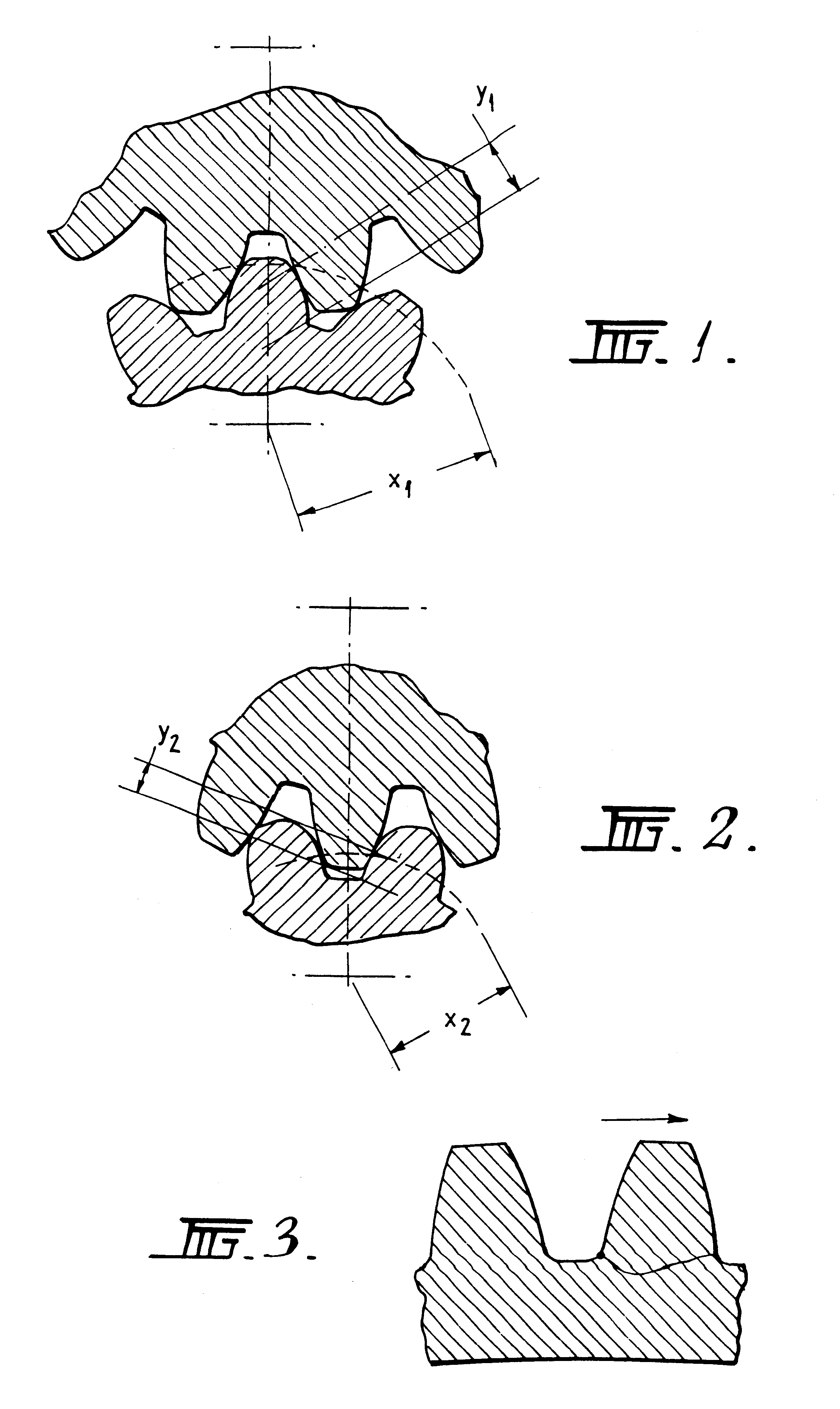
As described above, FIGS. 1 to 3 illustrate "un-timed" meshing between a side gear and a pinion gear, "timed" meshing between a side gear and a pinion gear and a common form of tooth failure in a gear tooth, respectively, the direction of tooth load being illustrated by the arrow.

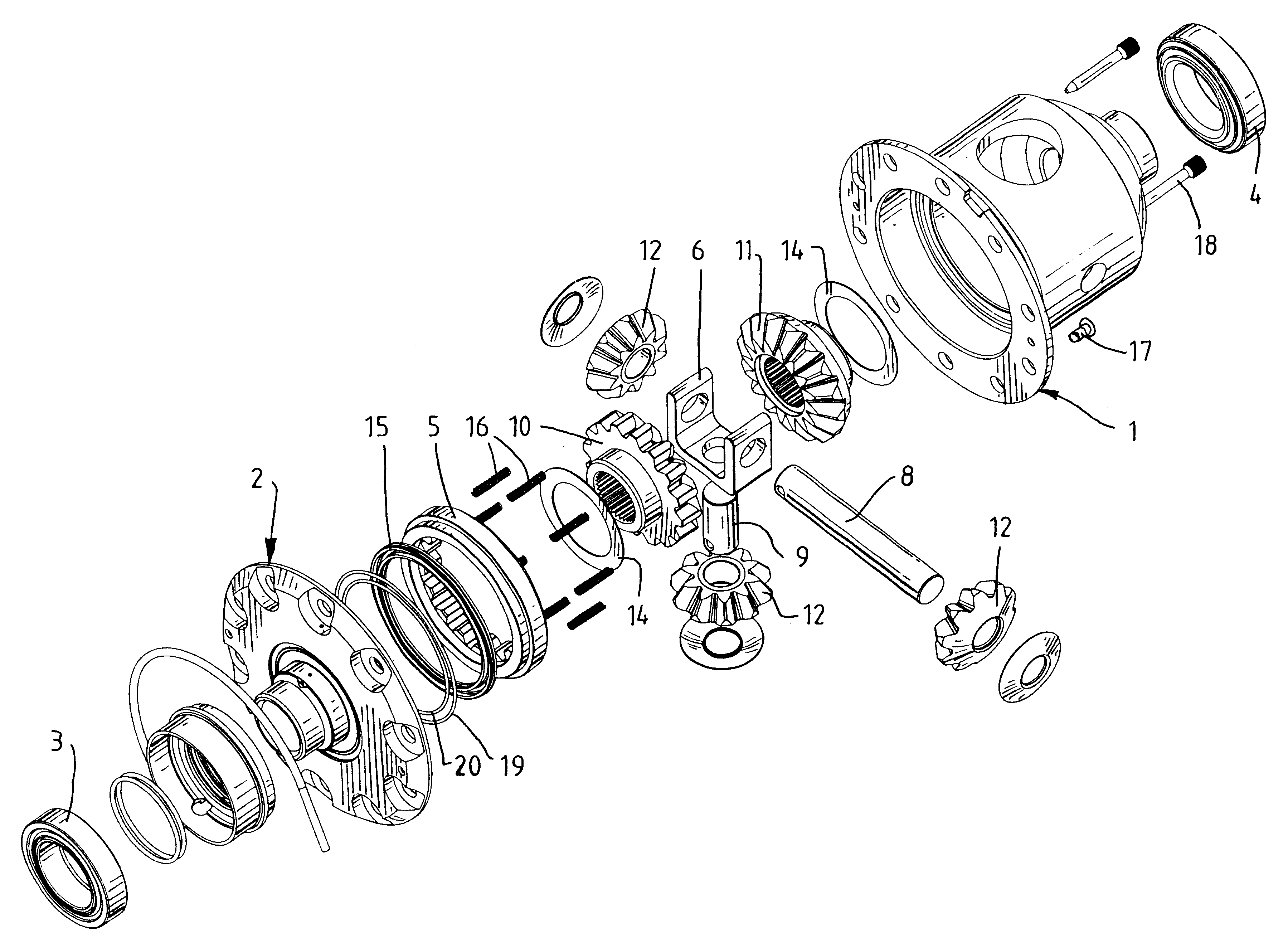
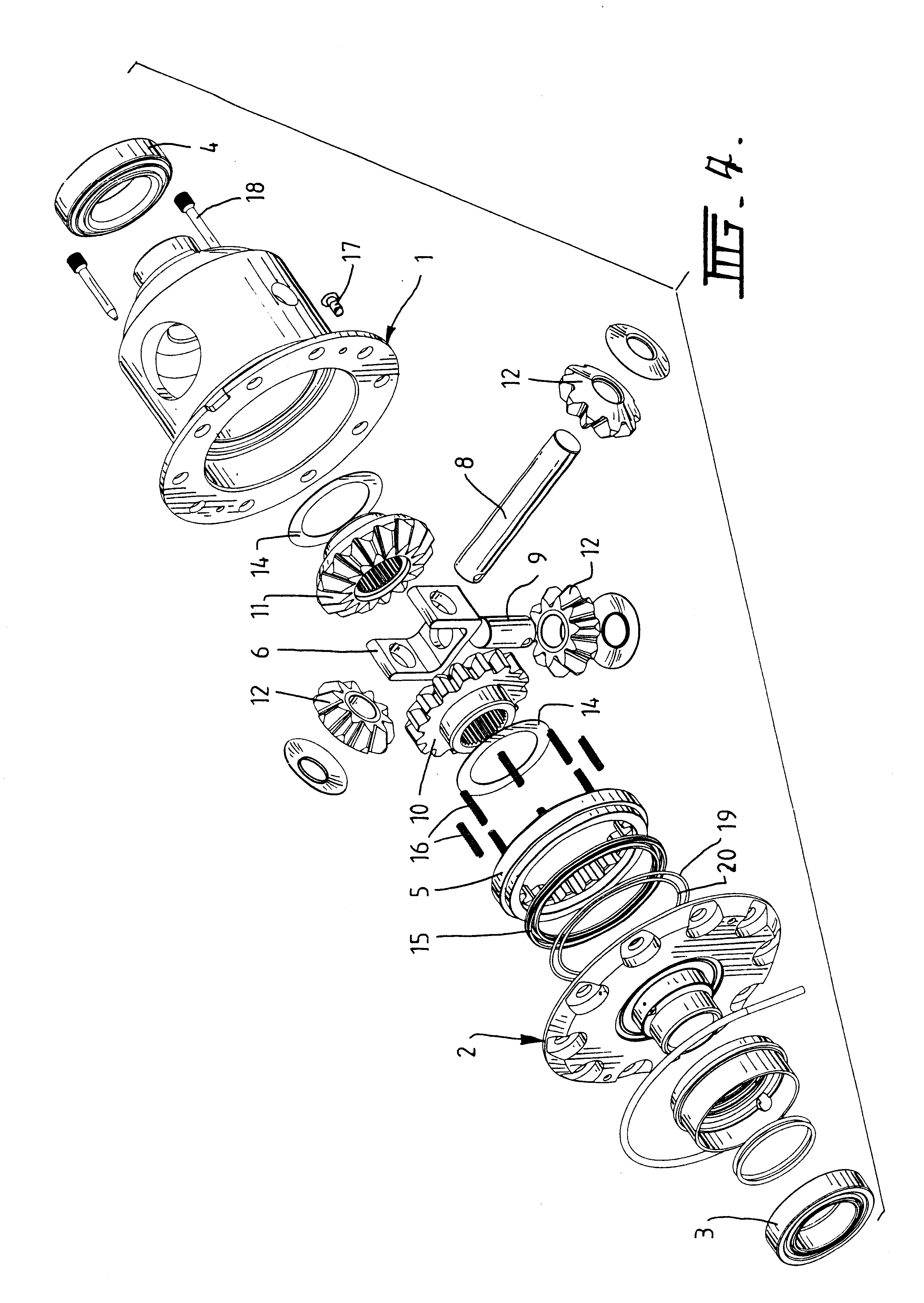
Referring now to FIGS. 4 and 5 of the drawings, a locking differential embodying the invention is illustrated in exploded perspective views. The differential includes a differential carrier or housing 1 and a flange cap 2 which is formed with locking gear 2A, as illustrated in FIG. 5. The flange cap 2 is secured by bolts (not shown) to the flange of the housing 1 to close the differential housing 1.

Thrust bearings 3 and 4 on the housing 1 and the flange cap 2 mount the housing 1 in a differential casing (not shown), and a clutch gear 5 slidably engages the locking gear 2A and is movable between the unlocked position and the locked position by means of an annular piston 15 against the action of clutch return...


PUM


Abstract

A locking differential including a differential carrier or housing 1 closed by a flange cap 2 engaging locking gear 2A, the housing 1 and flange cap 2 supporting side gears 10 and 11 which mesh with pinion gears 12 supported by cross shafts 8 and 9, the cross shafts engaging mounting holes in the housing 1, each pinion gear having an even number of teeth, and each side gear having a number of teeth which is a multiple of two where two pinions are at 180° to each other, three where three pinion gears are at 120° to each other, four where three or four pinion gears are at 90° to each other, or five where five pinions are at 72° to each other, the locking means further including a clutch gear 5 which slidably engages the locking gear 2A and the teeth on side gear 10 in the locked position, the cross shafts 8 and 9 being in a fixed relationship to the locking gear 2A.

Description

This invention relates to locking differentials in which the meshing configuration of the teeth of the side gears and pinions of the locked differential are improved.Background of the InventionIn our U.S. Pat. No. 4,759,232, Roberts, we have described an improved locking differential capable of remote pneumatic actuation and including a locking ring housed within the differential carrier around one of the bevel gears and connected to a piston actuator located around the other of the bevel gears and connected to the locking ring by a sleeve. This locking system has enjoyed significant commercial success since it provides a locking differential mechanism which can be fitted to an existing differential housing with minimal modification to allow the remote pneumatic operation.As a result of the extremely confined space within the differential carrier, the actuator and locking ring have always needed to be located on opposite sides of the pinion gear which increases the manufacturing ope...

Claims


Application Information

Patent Timeline
IPC IPC(8): F16H48/30F16H48/00F16H48/08F16H48/20F16H48/24F16H48/32F16H48/34
CPCF16H48/08F16H48/24F16H48/30F16H48/34F16H2200/2071F16H2048/204F16H48/32
Inventor BONGARD, DANIEL JASON
Owner ARB CORP LTD
Why Eureka
Try Eureka