Floatable impeller for multistage metal working pump

a metal working pump and impeller technology, applied in the direction of machines/engines, stators, liquid fuel engines, etc., can solve the problems of difficult to achieve the precise dimension required, heavy weight of traditional multi-stage pumps made by casting, and bulky, etc., to achieve the effect of reducing friction loss, improving pumping efficiency, and reducing friction loss

Inactive Publication Date: 2002-06-04
IND TECH RES INST
View PDF10 Cites 19 Cited by
  • Summary
  • Abstract
  • Description
  • Claims
  • Application Information

AI Technical Summary

Benefits of technology

The diffuser is soldered to and supported by a diffuser collar. The diffuser collar includes a metallic diffuser metal working member which is integrally formed with a diffuser plastic member which in turn has a center hole to house a shaft sleeve therein. The shaft sleeve has a center bore to engage with the shaft. The shaft and shaft sleeve are rotating synchronously in the diffuser plastic member. There is a bakelite ring sandwiched between the diffuser plastic member and impeller plastic member. The structure set forth above makes rotation friction happen between plastic and plastic and m

Problems solved by technology

Traditional multistage pumps made by casting is heavy, bulky and has lower pumping efficiency.
However metal working pump shell is usually made by stamping or pressing and is difficult to reach precise dimension required.
The pump shell is prone to deformation under high pumping pressure.
The sealing is prone to malfunction and result in leaking.
The high speed rotating impeller is easy to make friction against the stationary pump shell and result in lowering pump service l

Method used


Image

  • Floatable impeller for multistage metal working pump
  • Floatable impeller for multistage metal working pump
  • Floatable impeller for multistage metal working pump

Examples


Embodiment Construction

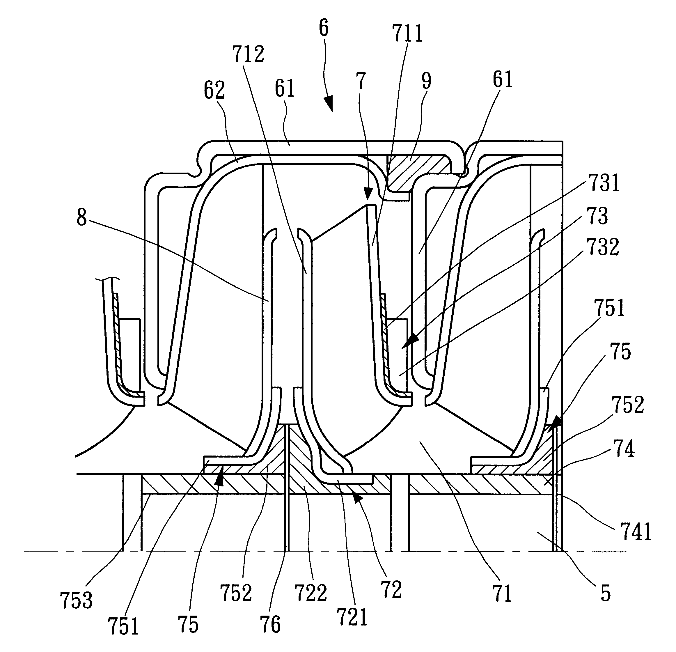
Referring to FIG. 1, the multistage metal working pump according to this invention includes a plurality of pump shell units 6 (two sets of adjacent pump shell units are shown in the figure) stacked in series on a shaft 5. Each pump shell unit 6 includes a diffuser unit (constitutes an outer shell 61, inner shell 62 and a diffuser 8), an impeller 7 and a seal ring 9. The shaft 5 drives the impeller 7 to rotate in the shells 61 and 62 to draw fluid to flow from an impeller inlet 71 through the diffuser 8 and to a next stage pump shell unit. The structure of the shaft 5, shells 61, 62, seal ring 9 and diffuser 8 are known in the arts and form no part of this invention, thus will be omitted in the description below.

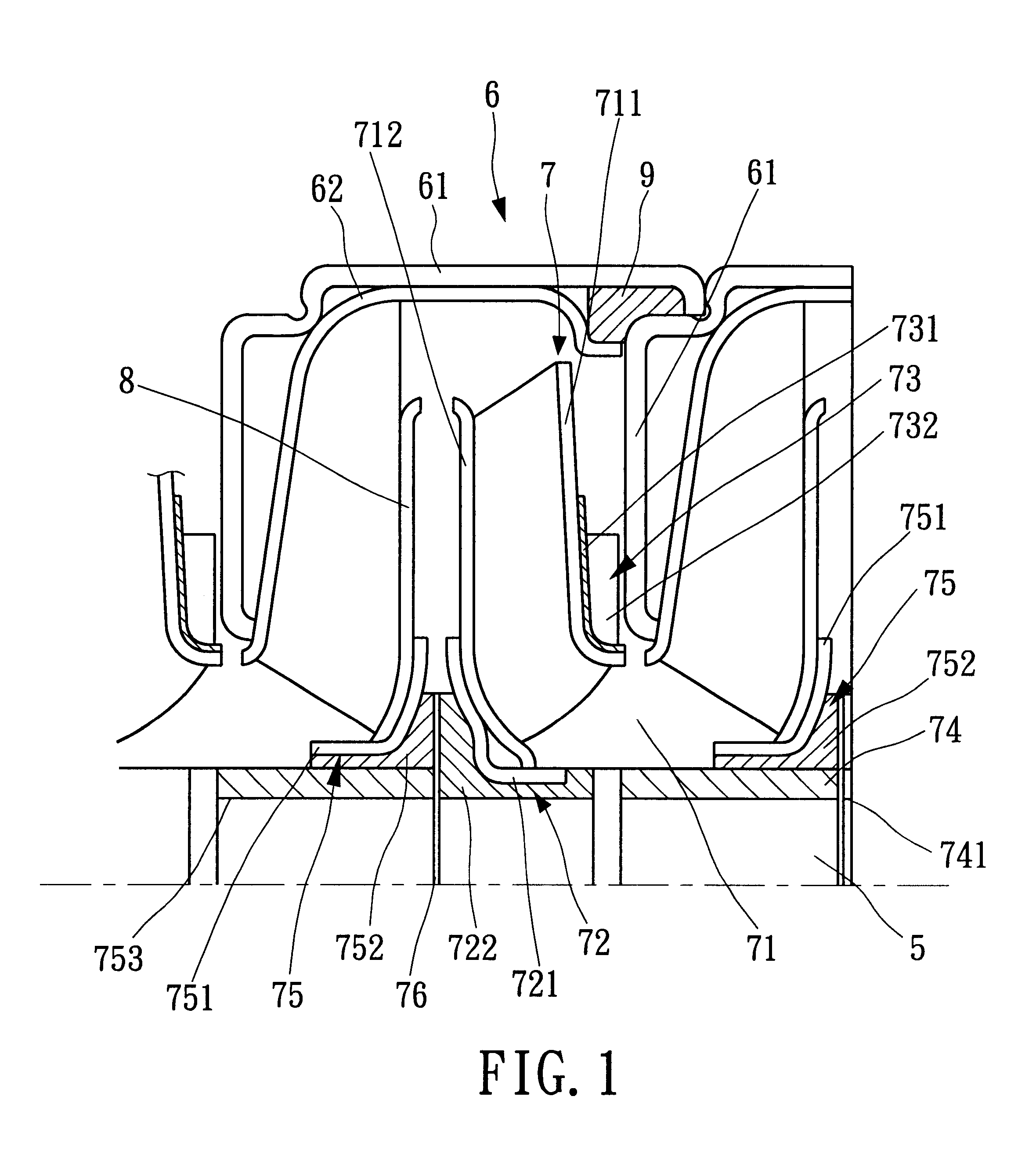
Details of the floatable impeller structure are shown in FIGS. 1 through 6. The metal working impeller 7 includes a front wall 711, a rear wall 712 and a plurality of blades (not marked in figures) sandwiched between the front and rear wall. The impeller 7 further has an impe...


PUM


Abstract

A floatable impeller for multistage metal working pump includes an impeller hub which has an impeller metal working member supporting a rear wall of the impeller and an impeller plastic member integrally formed with the impeller working member. The impeller plastic member is engaged with and driven by the pump shaft. The impeller has a front wall attached with an impeller thrust ring which has a thrust metal working member integrally formed with a thrust plastic member located in front of the impeller front wall. The thrust plastic member serves as a bearing when rotating against a metallic pump shell of an adjacent pump unit for reducing friction loss. The impeller hub has axial grooves formed in the inside wall. The thrust plastic member has radial slots formed in the sidewall. The grooves and slots may collect and discharge grits and sands carried by fluid and generated by friction for reducing friction, improving pumping efficiency and enhancing pump durability.

Description

FIELD OF THE INVENTIONThis invention relates to a floatable impeller for multistage metal working pump and particularly for submersible pump (water-sunken pump) that has thrust bearing means movable axially along the shaft for a desired distance for reducing rotation friction between the impeller and pump shell and to facilitate assembly.DESCRIPTION OF THE PRIOR ARTConventional multistage centrifugal pumps (such as submersible pumps) usually have a plurality of pump shell units and impellers stacked in series along a shaft. The shaft rotates the impellers against the pump shells and generates centrifugal force for fluid to flow in the passage through the pump shells. Traditional multistage pumps made by casting is heavy, bulky and has lower pumping efficiency. They are increasing being replaced by metal working pumps.However metal working pump shell is usually made by stamping or pressing and is difficult to reach precise dimension required. The pump shell is prone to deformation un...

Claims


Application Information

Patent Timeline
IPC IPC(8): F04D29/00F04D29/02F04D29/22F04D29/18
CPCF04D29/2222F04D29/026F05D2300/43
Inventor CHIEN, HUAN-JANOU, PAO-YINKAO, SHU-FENLIAW, RONG-JAU
Owner IND TECH RES INST
Why Eureka
Try Eureka