
Calibration system and displacement measurement device

a technology of displacement measurement and calibration system, which is applied in the direction of electric programme control, instruments, program control, etc., can solve the problems of prior art system numerous problems, robots that cannot actually achieve the commanded cartesian coordinates, and loss of "absolute robot positional accuracy"

Inactive Publication Date: 2002-06-18
DYNALOG
View PDF5 Cites 95 Cited by
  • Summary
  • Abstract
  • Description
  • Claims
  • Application Information

AI Technical Summary

Problems solved by technology

Therefore, a loss of "absolute robot positional accuracy" results, for example, when programming an individual industrial robot "off-line" (ie. programming by indicating Cartesian coordinates for a desired robot position rather tan driving the robot to that desired position), due to use of the nominal parameters of the robot (instead of the "as built" parameters) by the robot controller: the robot does not actually achieve the commanded Cartesian coordinates of position in space desired by the robot operator / programmer.
This prior art system has numerous problems and in fact is generally only found in non-commercial facilities.
Furthermore, this prior art system depends upon the accuracy of the 3-dimensional positional information, which means by nature of the triangulation process that the positional information "degrades" in several portions of the robot's operational envelope (particularly at the boundaries of such operational envelope).
Therefore, in some instances, in fact, the absolute positional accuracy of the robot was not improved but rather worse than before the calibration procedure was performed with this prior art system.
Moreover, in addition to the restrictions upon overall accuracy of this prior art system attributable to triangulation and use of this "derived" 3-dimensional data, the linear displacement measurement devices themselves restricted measurement accuracy due to inherent design flaws.
By definition, as the cable can simply not bend at a "sharp" angle, the "rounding" of the cable when making contact with the edge of the exit hole contributed to error in the measurement data.
Furthermore, this prior art system does not contain a design element to defeat overlap of the measurement cable as it retracts into the housing.
This design issue concerning overlap contributes significantly to overall system error as the length of the cable extended is calculated based upon the assumed known and constant radius of the drum upon which the measurement cable retracts.
However, as this groove method requires "spacing" on the drum surface, the groove method naturally restricts the amount of measurement cable which can be held by each linear displacement device, and consequently restricts the amount of the robot's operational envelope in which measurements can be recorded.
Finally, the groove method does not prevent cases in which the cable "jumps" out of one groove and rests on top of another portion of the drum at unpredictable intervals.
Extension bars permit the nominal length of the ball-bar to be increased in order to reach more of the robot's operational envelope, but these extension bars add significant weight (and corresponding force) at the measurement point and therefore degrade the accuracy of the measurement data recorded with the LVDT mechanism.
However, this prior art system alternatively permits, although the process is cumbersome, the operator to "serialize" the procedure by commanding the robot to travel on a spherical shell while only one ball-bar is connected between its end point and table.
In fact, the inventors of this prior art system state that the limited reach of the ball-bar substantially restricts the positional freedom that can be achieved during the calibration process.
Unfortunately, the requirement that a plurality of magnetic chucks be employed prevents use of this prior art system to perform robot calibration automatically (ie. without robot operator / programmer intervention).
These pulleys have a known radius, and eliminate the problem of the cable exiting through a hole at different angles, although they add some inherent complexity in the measurement process, since the measurement cable length no longer represents a straight line from one point to the other.
The result of this situation would be a reduced rotational displacement about the drum when the cable is either extended or retracted, thereby providing inaccurate information concerning measurement cable displacement.
However, this increase the size of the displacement measurement device itself, proportionally to the amount of coils around the drum.
As a result, this prior art system exhibits some "degradation" of the converted measurement data, similar to the previously discussed prior art system which employs three linear displacement devices to report 3-dimensional position information.

Method used


Image

  • Calibration system and displacement measurement device
  • Calibration system and displacement measurement device
  • Calibration system and displacement measurement device

Examples


Embodiment Construction

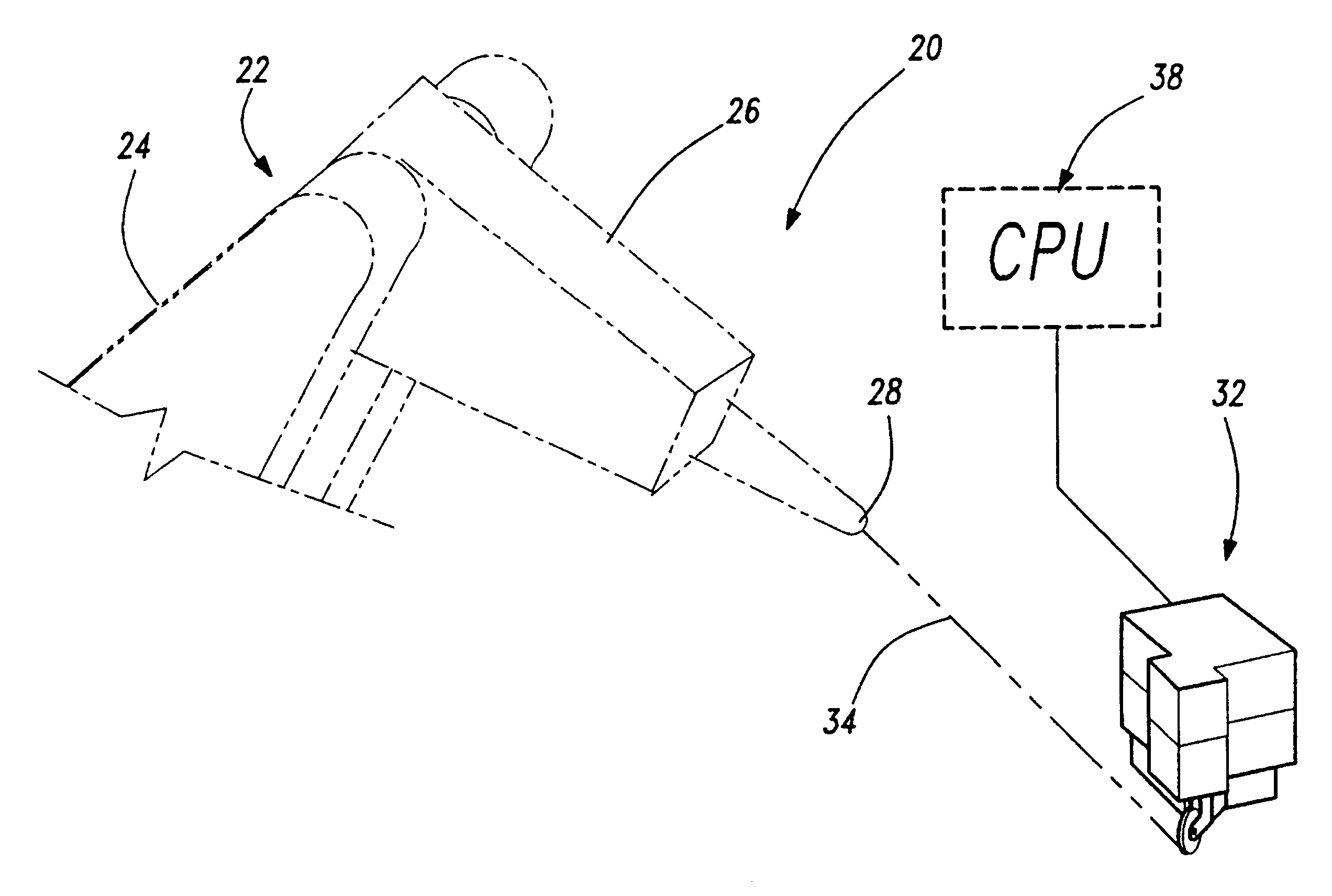
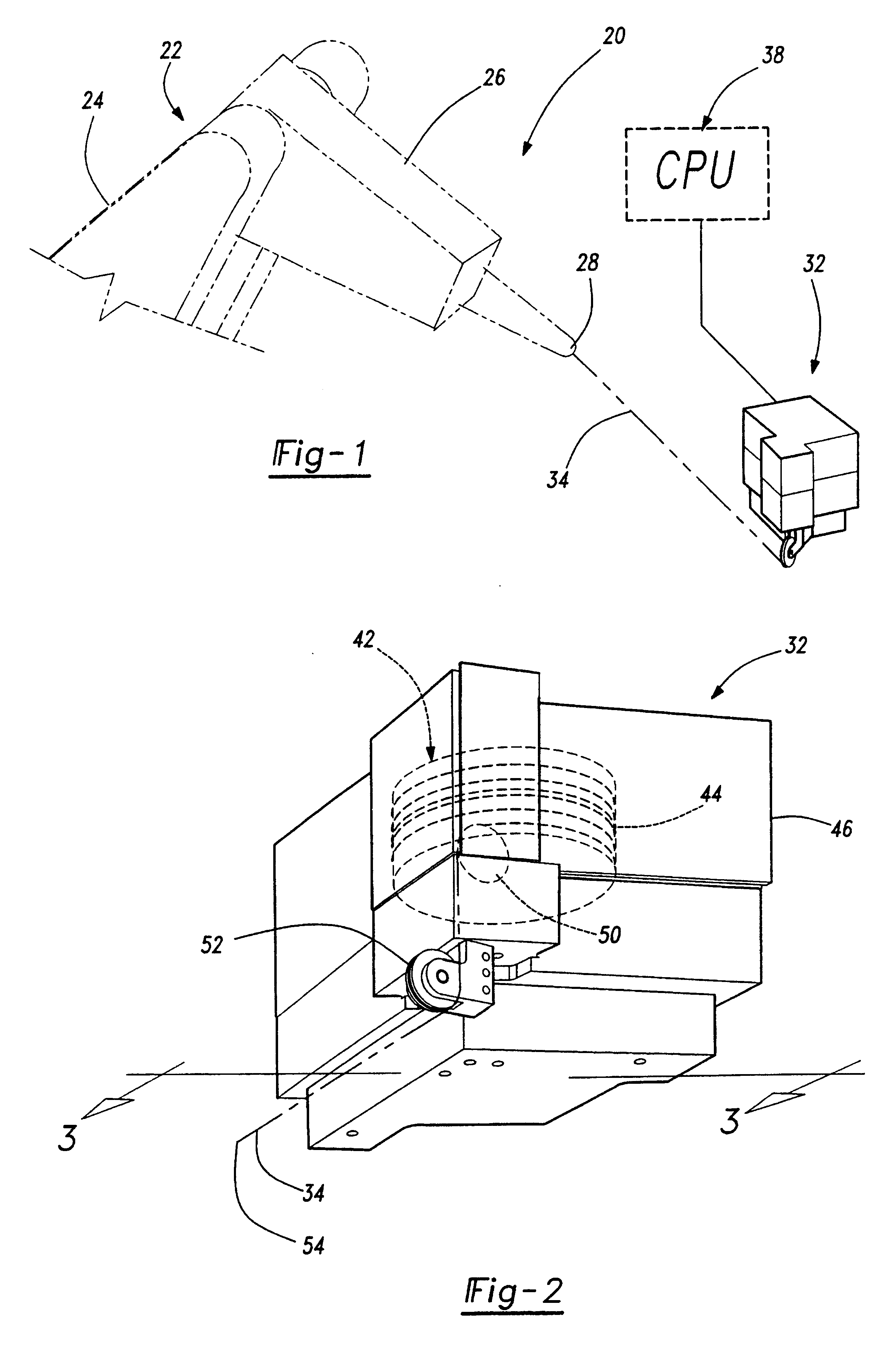
does assume the displacement measurement device, 32, to be located at one generally unknown position relative to the robot, 22. Also, the end of the elongated member, 34, is at one originally unknown position relative to the end of the arm, 26. These originally unknown parameters are calculated together with the actual robot geometry parameters through the calibration software.

In an alternate embodiment, the displacement measurement device can be placed at a minimum of three location on a single fixture holding a production part, these different locations being accurately known with respect to one common coordinate frame. In such an embodiment, the calibration system software of the present invention will identify the mathematical relation in six degrees of freedom between that common coordinate frame and the frame attached to the end of the arm, 26.

In yet another embodiment, the end of the elongated member, 34, can be attached to a minimum of three locations on an end effector whic...


PUM


Abstract

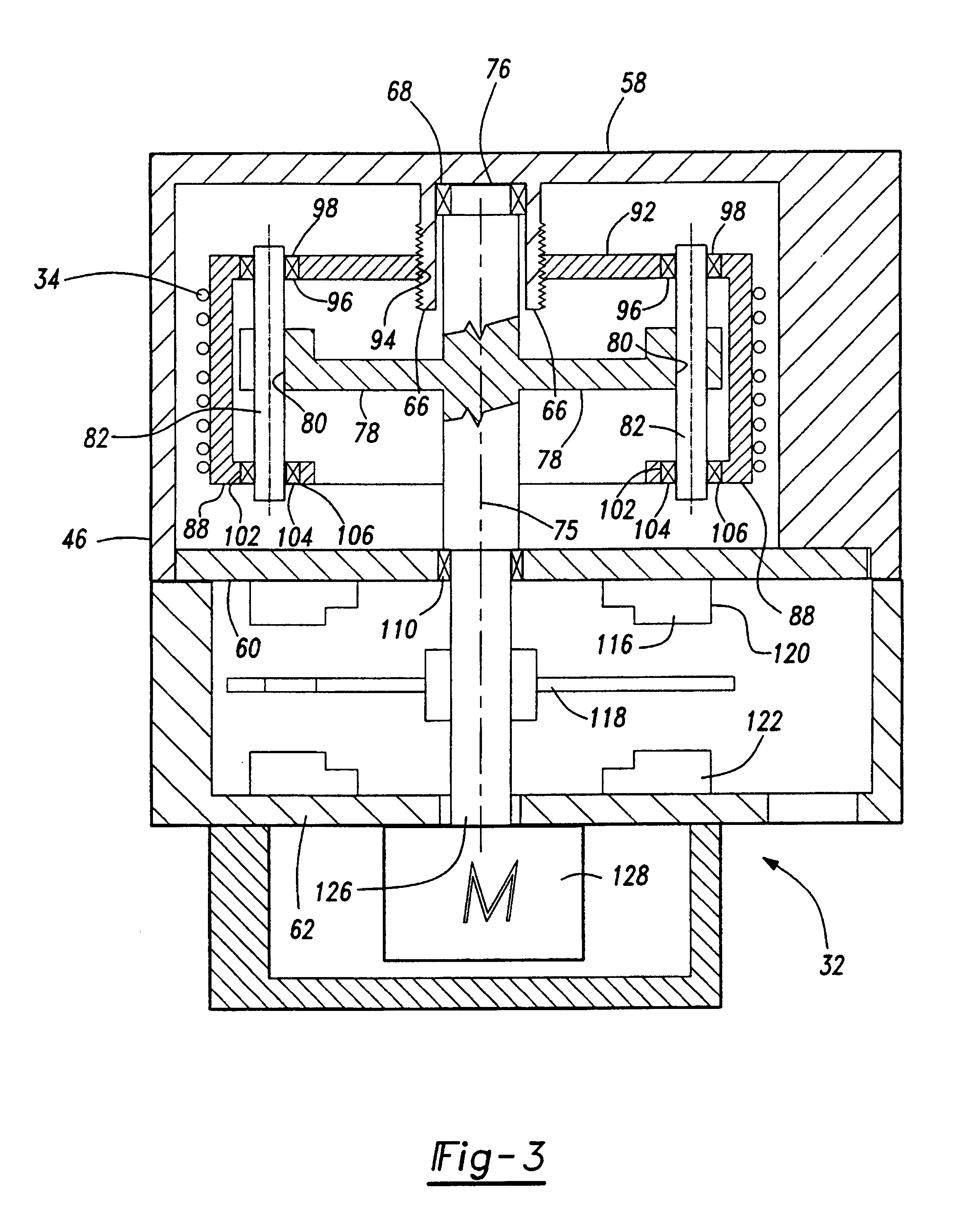
An improved system (20) for the calibration of a robot system. The system (20) comprising a linear displacement measurement device (32) in conjunction with a robot calibration system. The linear displacement measurement device (32) comprising an elongated member (34), a drum, a shaft, a drum displacement mechanism and a drum rotation sensor. The drum is displaced axially upon the shaft as the drum rotates when the elongated member (34) is moved. The drum rotation sensor provides accurate information regarding the distance the elongated member (34) travels. The displacement measuring device (32) is used in an iterative manner with the calibration system (20) for the purpose of the calibration of a robotic device (22).

Description

1. Field of the InventionThe present invention relates to a robot calibration system with a linear displacement measuring device.2. Description of the Related ArtThere are many known calibration systems for improving the positional accuracy of an industrial robot which are based upon a kinematic model of the robot. The movement of a single robot is controlled by algorithms executed within the processor for the robot (the robot's "controller"). These algorithms are based upon a mathematical model of the robot's geometry based on ideal, nominal parameters (ie. length of each link, twist angles between links, etc). However, the actual parameters (also known as "as built" parameters) of an individual industrial robot differ from the nominal ones due mainly to tolerances applied to each component in both the machining of components, sub-assembly of components, and final assembly of an industrial robot. Consequently, each individual robot of the same production model generally possesses a...

Claims


Application Information

Patent Timeline
IPC IPC(8): B25J9/16
CPCB25J9/1692G05B2219/39009
Inventor DE SMET, PIERRE
Owner DYNALOG
Learn More