Fiber optic illumination and detection patterns, shapes, and locations for use in spectroscopic analysis

a fiber optic and detection pattern technology, applied in the direction of instruments, optical elements, bundled fibre light guides, etc., can solve the problem that the device has provided less than satisfactory results

Inactive Publication Date: 2002-06-25
GLT ACQUISITION
View PDF11 Cites 310 Cited by
  • Summary
  • Abstract
  • Description
  • Claims
  • Application Information

AI Technical Summary

Problems solved by technology

However, such known devices have pro

Method used


Image

  • Fiber optic illumination and detection patterns, shapes, and locations for use in spectroscopic analysis
  • Fiber optic illumination and detection patterns, shapes, and locations for use in spectroscopic analysis
  • Fiber optic illumination and detection patterns, shapes, and locations for use in spectroscopic analysis

Examples


Embodiment Construction

Optimization

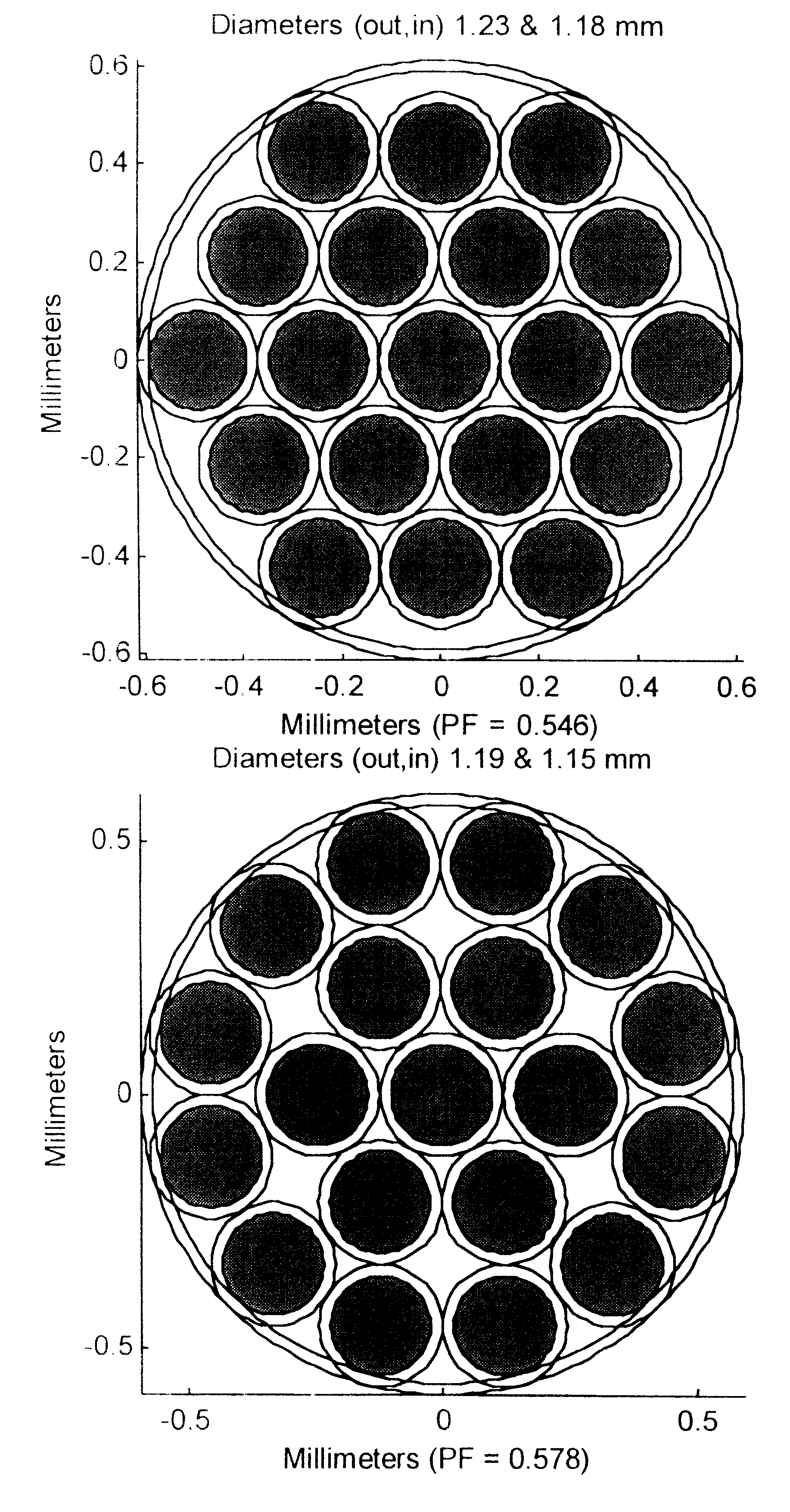
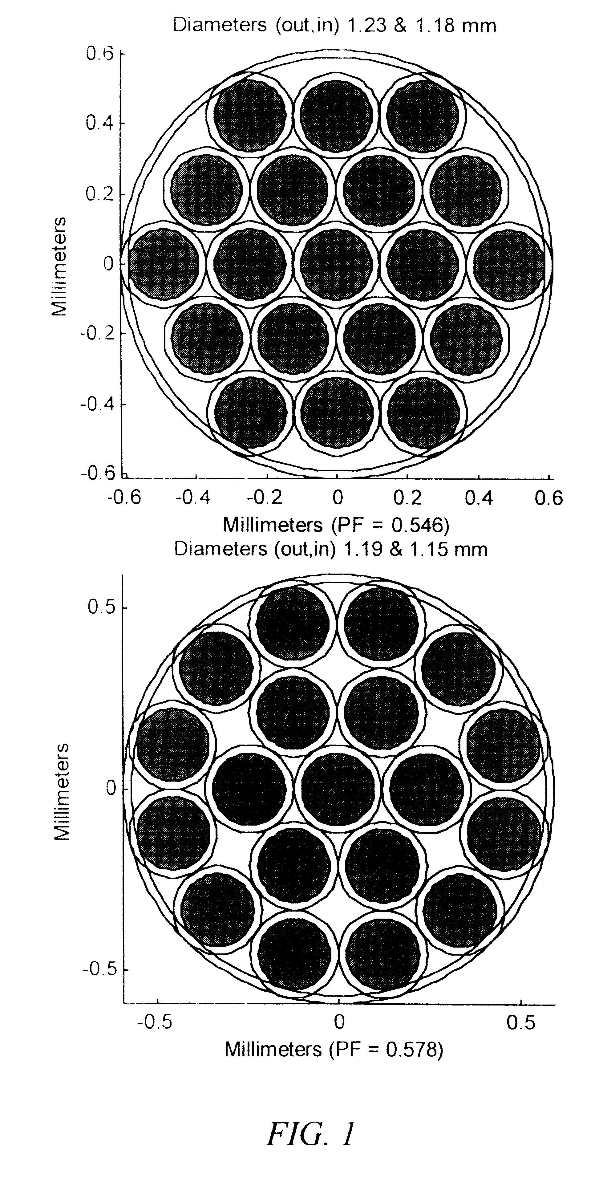
Generally, it is desirable to design for the best or optimal solution, indicating the lack of ability to improve upon a design. In the presence of design constraints, however, the term optimal solution is often employed meaning the best solution, given the tradeoffs and practical considerations. The term optimization, as used herein, means the maximization of a cost or evaluation function in some manner based upon a pre-defined set of mathematical operations. With regard to the preferred embodiment of the invention described herein, the evaluation function is an estimate of the modeled signal-to-noise ratio. The optimization criterion maximizes the sum of this evaluation function in a portion of the combination band (2100-2250 nm) that is deemed to be representative of the glucose molecule's absorption in that region.
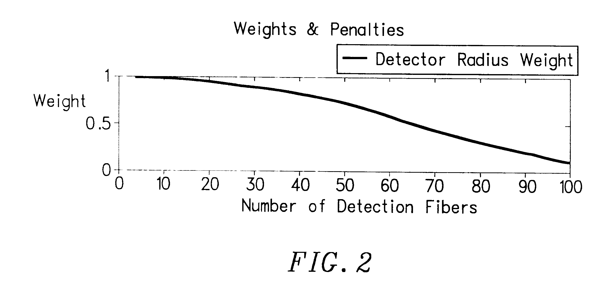
Weights & Penalties

Detector Penalty

As discussed above, light from the detector fibers is focused onto the detector using a two lens system. The detector fib...


PUM


Abstract

The invention provides a design process that is used in the determination of the pattern of detector and illumination optical fibers at the sampling area of a subject. Information about the system, specifically a monochromator (e.g. to determine the optimal number of fibers at an output slit) and the bundle termination at a detector optics stack (e.g. to determine the optimal number of fibers at the bundle termination), is of critical importance to this design. It is those numbers that determine the ratio and number of illumination to detection fibers, significantly limiting and constraining the solution space. Additional information about the estimated signal and noise in the skin is necessary to maximize the signal-to-noise ratio in the wavelength range of interest. Constraining the fibers to a hexagonal perimeter and prescribing a hex-packed pattern, such that alternating columns contain illumination and detection fibers, yields optimal results. In the preferred embodiment of the invention, two detectors share the totality of the detection fibers at the sampling interface. A third group of detection fibers is used for classification purposes.

Description

1. Technical FieldThe invention relates to the use of fiber optics for the illumination of analyte samples and for the detection of signals present at such analyte samples. More particularly, the invention relates to fiber optic illumination and detection patterns, shapes, and locations for use in the noninvasive global-estimation of analytes, such as blood glucose.2. Description of the Prior ArtTo those knowledgeable in the art, the size, arrangement, and number of detection and illumination optical fibers at the interface of a probe designed to launch and collect light from a tissue sample, such as human skin, significantly impacts the received signal.Various attempts have been made in the past to provide devices that illuminate and collect light from a tissue sample. See, for example, K. Maruo, K. Shimizu, M. Oka, Device For Non-Invasive Determination of Glucose Concentration in Blood, European Patent Application No. EP 0 843 986.However, such known devices have provided less tha...

Claims


Application Information

Patent Timeline
IPC IPC(8): G01N21/47G01N21/35G02B6/04
CPCG01N21/474
Inventor GARSIDE, JEFFREY J.MONFRE, STEPHENELLIOTT, BARRY C.RUCHTI, TIMOTHY L.KEES, GLENN AARONGROCHOCKI, FRANK S.
Owner GLT ACQUISITION
Why Eureka
Try Eureka