
Background read scanning with defect reallocation

Inactive Publication Date: 2002-06-25
HEWLETT PACKARD DEV CO LP
View PDF22 Cites 52 Cited by
  • Summary
  • Abstract
  • Description
  • Claims
  • Application Information

AI Technical Summary

Problems solved by technology

Thus, these devices are complex electro-mechanical devices and, as such, can suffer performance degradation or failure due to a single event or a combination of events.
The first class is the "catastrophic" type of failure which causes the drive to quickly and unpredictably fail.
These failures can be caused by static electricity, handling damage, or thermal-related solder problems.
Certainly, there is little hope of predicting these types of failures once the drive it put in service.
The second class of failures result from the gradual decay of other electrical and / or mechanical components within the drive after it is put in service.
While this type of defect correction is adequate to catch defects as the sectors are read, it does nothing to catch latent defects in sectors that have not been read.
Thus, this technique is only adequate for on the fly correcting.
1. Do nothing but wait for the drive to fail and then replace the drive. This is the easiest but will cause much down time and lost data when the drive fails.
2. Practice periodic preventative maintenance and simply replace the drive before it fails. This is somewhat effective in reducing unscheduled down time but suffers from the high cost of replacing drives before their life has been exhausted.
3. Use redundancy or backups. This technique is also effective in reducing unscheduled down time. It does not require the drives to be replaced before they fail, but suffers from the cost of having duplicate or additional hardware.
4. Rely on the disk drives built in error correction schemes to make corrections as the data is read.
5. Use Predictive Failure Analysis (PFA). Because this second class of failure can occur over time, it is possible to predict these types of failures by monitoring conditions of the drive.
Because disk drives are inherently defect prone, error correction scans are performed on the disk drives at the factory for marking any defective sectors before the drives are put into service.
If any of the syndromes are non-zero, an error has occurred.
If the algorithm is not successful, a pending defect will be added to the defect list.
Any subsequent read to the original logical block will return an error if the read is not successful.

Method used


Image

  • Background read scanning with defect reallocation
  • Background read scanning with defect reallocation
  • Background read scanning with defect reallocation

Examples


Embodiment Construction

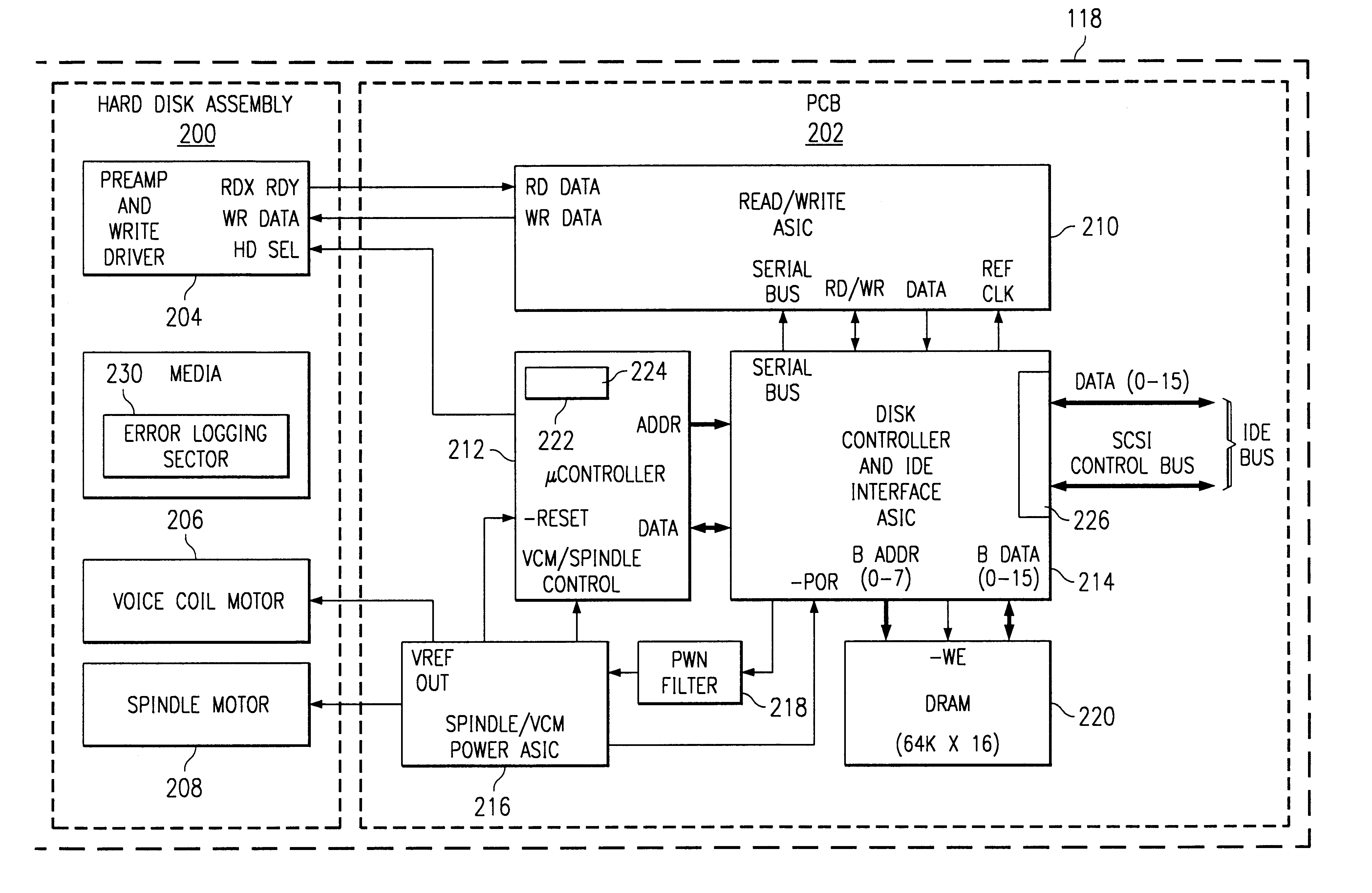
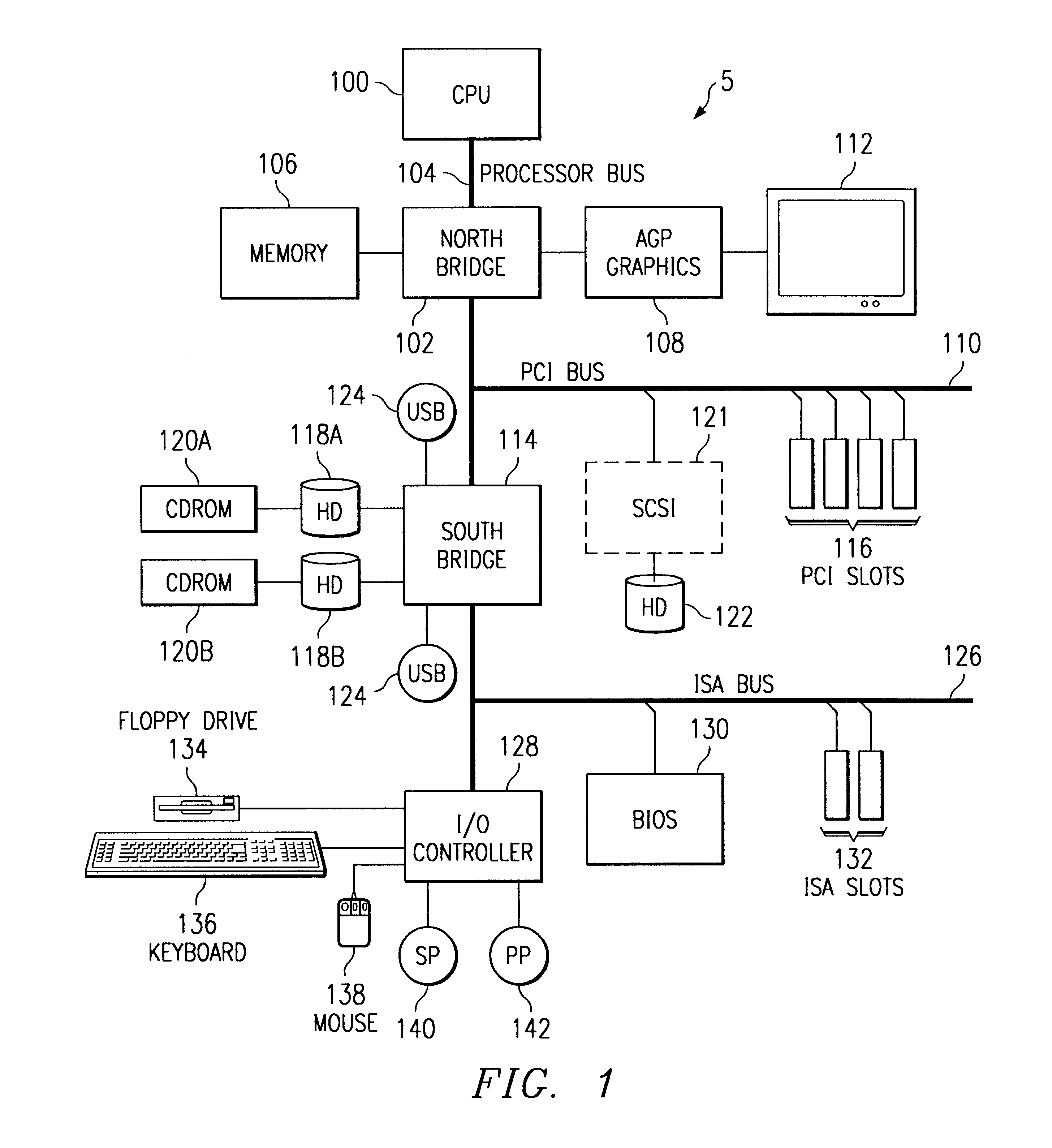
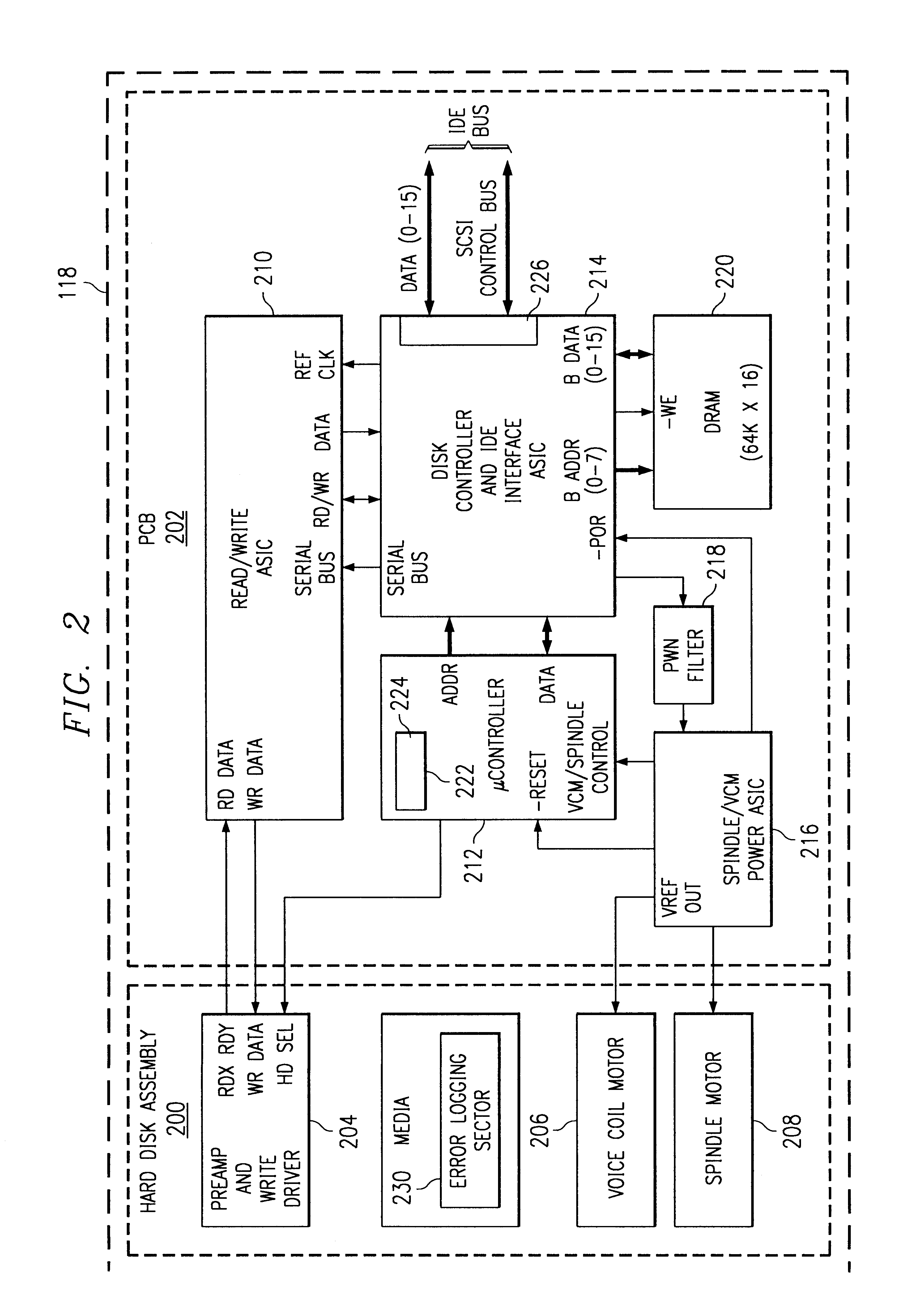
Referring first to FIG. 1, there is illustrated a computer system S, for example a personal computer (or "PC"). While the computer system S shown is of an International Business Machines (IBM) PC variety, the principles of the present invention are equally applicable to other computer platforms or architectures, such as those associated with by IBM, Apple, Sun and Hewlett Packard. While the following description is limited to typical components of an IBM-PC platform, it is understood that corresponding components from alternative platforms could be used. For example, in an IBM-PC an Intel processor is typical whereas in an Apple computer a Power-PC processor is typical. The invention is also applicable to other devices employing disk drives, such as printers, voice-mail systems and other specialized electronic devices.

As is conventional in the art, the computer system S includes a central processing unit (CPU) or, simply, processor 100, such as an Intel Pentium II microprocessor or ...


PUM


Abstract

A method, apparatus and computer system for correcting errors and defects in a storage device. The storage device includes media for storing data. A periodic read scan is performed to test the data. If a repeatable error is found, the data is moved to a new sector from a pool of available sectors. Defects are counted and identified in a defect list for reporting to the host. The storage device is scannable is small segments to minimize impact on performance.

Description

1. Field of the InventionThe present invention relates generally to disk fault correction techniques for storage devices and, more particularly, to a method of correcting disk drive media faults while the hard drive is idle.2. Description of Related ArtThe vast majority of personal computer (PC) systems available today come equipped with a peripheral data storage device such as a hard disk (HD) drive. Hard disks are comprised of rigid platters, made of aluminum alloy or a mixture of glass and ceramic, covered with a magnetic coating. Platters vary in size and hard disk drives generally come in two form factors, 5.25 in or 3.5 in. Typically, two or more platters are stacked on top of each other with a common spindle that turns the whole assembly at several thousand revolutions per minute. There is a gap between the platters, making room for a magnetic read / write head, mounted on the end of an actuator arm. There is a read / write head for each side of each platter, mounted on arms whic...

Claims


Application Information

Patent Timeline
IPC IPC(8): G11C29/00G11B20/18
CPCG11B20/1816G11B20/1833G11B20/1883G11B2220/20G11B2020/1836G11B2020/1893G11B2020/1823
Inventor LENNY, THOMAS R.CHEN, EDWARD J.
Owner HEWLETT PACKARD DEV CO LP
Learn More