Window, muntin and method

a technology applied in the field of muntin and glass, can solve the problems of fog-like effect, sometimes appearing in ig windows, and not providing support for muntins, and achieve the effect of easy manufacturing

Inactive Publication Date: 2002-07-09
CUSTOM GLASS PRODS OF CAROLINA
View PDF10 Cites 19 Cited by
  • Summary
  • Abstract
  • Description
  • Claims
  • Application Information

AI Technical Summary

Benefits of technology

While the science of glass and window making was advancing to allow larger panes of glass to be used, similar advances occurred in energy efficient windows, and hermetically sealed insulated glass windows have become increasingly popular. Such windows have parallel spaced panes of glass to provide insulation and increase energy conservation. These windows are commonly referred to as having insulated glass (IG) as two normal panes of glass are combined to form one pane of IG.
It is a further objective of the present invention to provide a muntin within an IG window which is pleasing to the consumer's eye.
It is still a further objective of the present invention to provide a muntin which is easy to manufacture through the use of Computer Aided Design (CAD) tools.
It is another objective to provide a muntin with low expansion characteristics and which has high memory.
It is yet another objective to provide an abrasive resistant muntin which is inexpensive to manufacture.

Problems solved by technology

These muntins do not provide any support; they are purely decorative.
Problems sometimes arise in IG windows as strong sunlight or heated temperatures raise the temperature inside the sealed glass.
Moisture in the muntin vaporizes and often recondenses on the inside surface of the glass pane, causing a fog-like effect which "clouds" the glass.
Because the glass is sealed, cleaning or rubbing will not remove this clouding.
The escape of moisture or liquid from the muntin is commonly referred to as "outgassing" and has been the cause of much dissatisfaction in the window fabrication and installation industry.
Likewise, this problem has required the replacement of many IG windows which become opaque with moisture.
While outgassing is less of a problem with conventional aluminum muntins, another problem arises in the manufacture of aluminum muntins for use in IG windows.
Aluminum can be difficult to bend using present technology, and some shapes are just not possible to create using aluminum.
Where aluminum can be used, it is frequently a multipiece assembly which raises manufacturing and assembly costs.
Other problems arise in the expansion and contraction of conventional muntins as they undergo temperature changes in installed windows.
At other times when the expanded muntin attempts to contract, the warp or buckle has become permanent and is unsightly.

Method used


Image

  • Window, muntin and method
  • Window, muntin and method
  • Window, muntin and method

Examples


Embodiment Construction

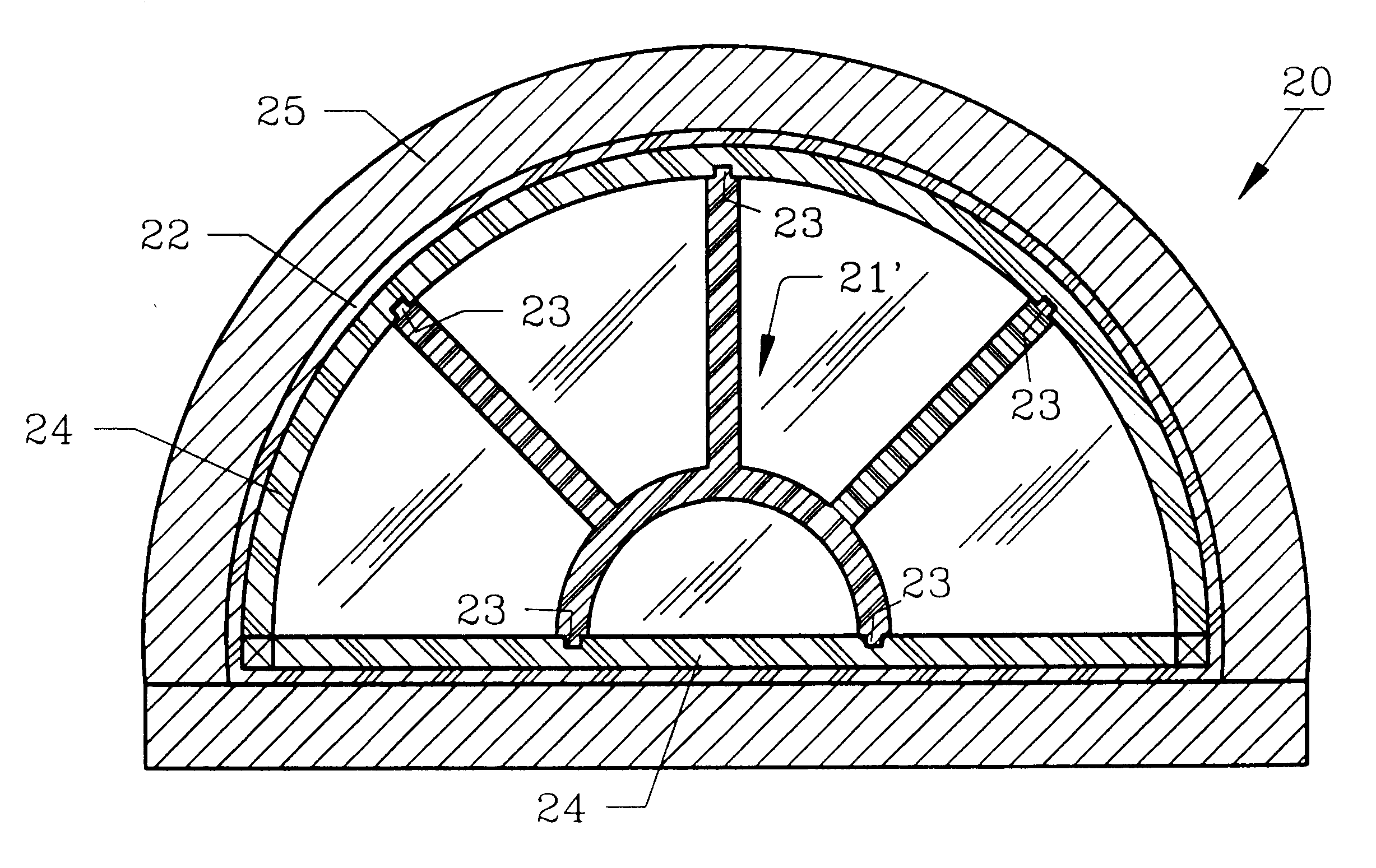
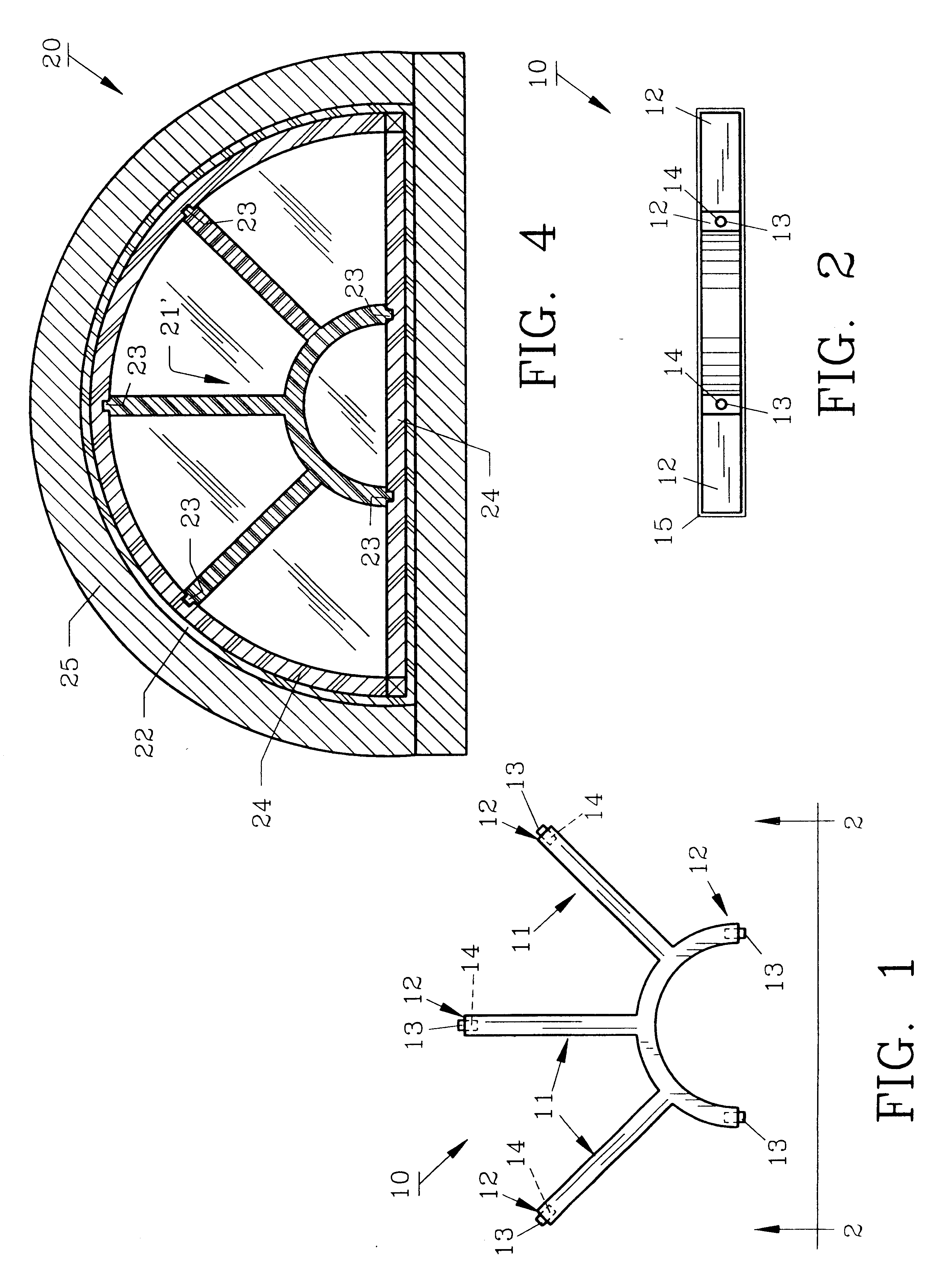
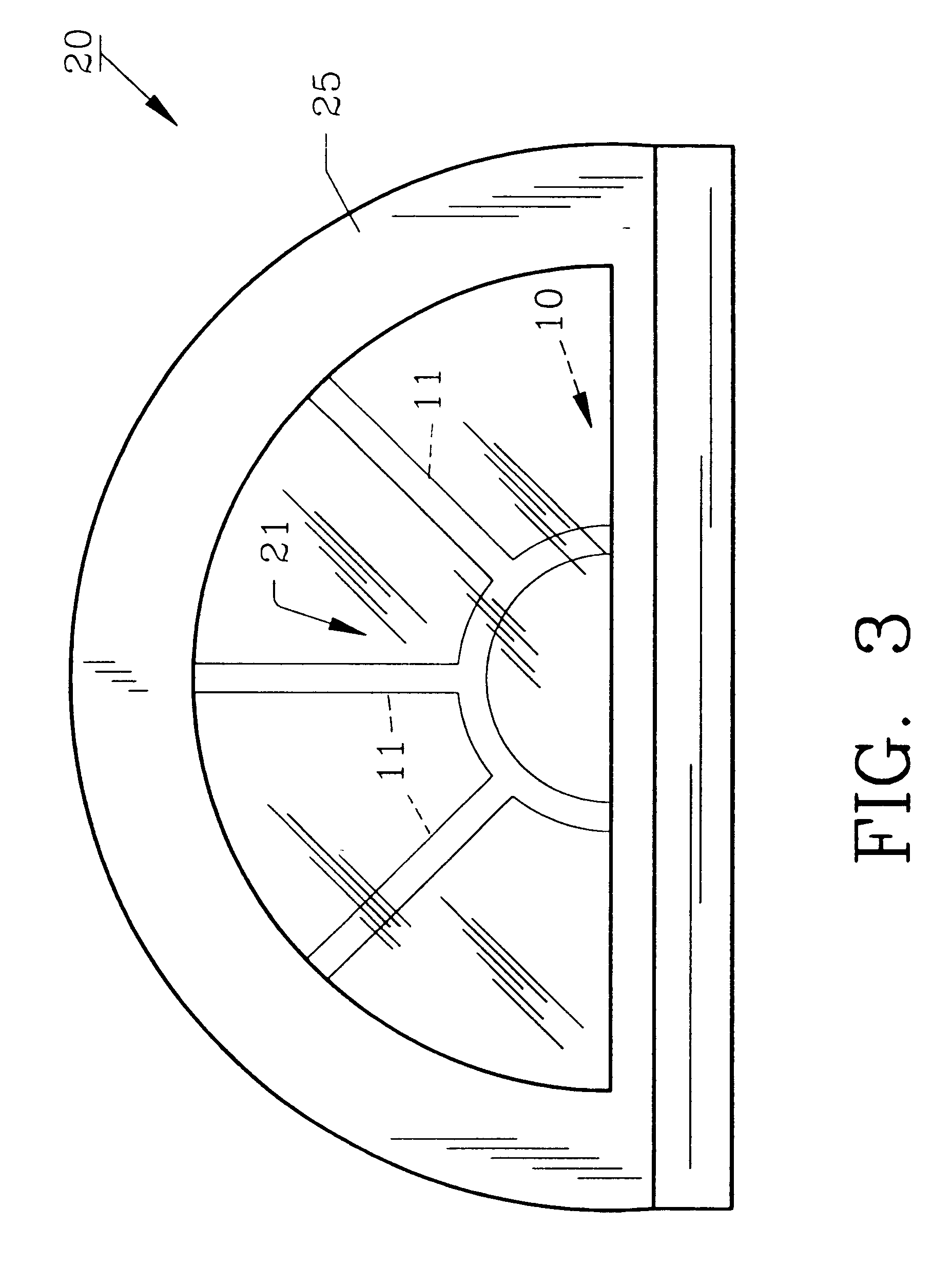
Turning now to the drawings, specifically FIGS. 1 and 2 show decorative window muntin 10, the preferred embodiment. Non-metal window muntin 10 is preferably machined from a 0.476 cm thick sheet of polystyrene, although other polymeric or non-metal materials such as polyurethane or wood may be acceptable, into a desired shape such as the radial display seen in FIG. 1, although other shapes and designs can be employed. Window muntin 10 includes a plurality of arms 11, each including end 12. Placed into each end 12 is cylindrical pin 13, which is preferably formed from aluminum 0.238 cm in diameter and 1.27 cm long. Pins 13 are received by cylindrical channels 14 which are preferably 0.238 cm in diameter and 0.635 cm deep, so that approximately one-half the length of each pin 13 extends from each channel 14. Pin 13 is centrally located on end 12 for optimum stability. Paint layer 15 (FIG. 2) completely surrounds and coats window muntin 10. Paint layer 15 is preferably conventional pigm...


PUM

PropertyMeasurementUnit
thickaaaaaaaaaa
diameteraaaaaaaaaa
diameteraaaaaaaaaa

Abstract

A non-metal window muntin formed from plastic or wood is described for use in hermetically sealed insulated glass windows. The process for forming the muntin includes machining polystyrene sheets which are painted with a latex pain and baked prior to use between sealed glass of the window.

Description

1. Field of the InventionThis invention pertains to a decorative window muntin contained between two hermetically sealed panes of glass and a method for making the same.2. Description of the Prior Art and Objectives of the InventionIn recent years, glass making and installing has progressed to allow large panes of window glass to be installed, whereas, previously, small panes were individually framed and supported within a window structure known by those in the industry as true divided lite (TDL). This TDL arrangement became unnecessary with utilization of large panes. For example, whereas, previously, a one meter by one meter window glass may have been made of nine individual panes of glass, now one pane is used.While the science of glass and window making was advancing to allow larger panes of glass to be used, similar advances occurred in energy efficient windows, and hermetically sealed insulated glass windows have become increasingly popular. Such windows have parallel spaced p...

Claims


Application Information

Patent Timeline
Patent Type & Authority Patents(United States)
IPC IPC(8): E06B1/00E06B3/66
CPCE06B1/006E06B3/6604B05D3/0254B32B37/16E06B7/00Y10T29/49623
Inventor REEDER, STEVEN L.REEDER, MICHAEL A.
Owner CUSTOM GLASS PRODS OF CAROLINA
Why Eureka
Try Eureka