
Lubricant cooling system for outboard motor

a technology for cooling systems and outboard motors, which is applied in the direction of machines/engines, marine propulsion, and vessel construction, etc., can solve the problems of poor lubricant performance, rapid degradation of lubricant quality, and high temperature fluctuation of lubricant being circulated within the engin

Inactive Publication Date: 2002-07-16
SANSHIN KOGYO CO LTD
View PDF34 Cites 30 Cited by
  • Summary
  • Abstract
  • Description
  • Claims
  • Application Information

AI Technical Summary

Problems solved by technology

The lubricant being circulated within the engine is prone to great fluctuations in temperature.
This elevated temperature creates problems, such as rapid degradation of lubricant quality and poor lubricant performance.
When the temperature of the lubricant is less than about 60.degree. C., it becomes difficult to pump and flows less freely through the lubricating system and through the engine.
On the other hand, when the temperature of the lubricant exceeds 80.degree. C., the lubricant begins to thin and becomes less effective in forming a protective film over moving components of the engine.
The fixed flow rate has a tendency of overcooling the lubricant when the engine is operating at a low speed or when the engine temperature is low.
However, this arrangement provides insufficient cooling to the lubricant when the engine temperature increases (i.e., during high speed operation).
While providing a viable solution, this system is not without its disadvantages.
For instance, fluctuations in the coolant flow rate may cause a negative load at the water pump.
The negative load may deteriorate the operability of the water pump over time.
Moreover, in watercraft being operated in saltwater environments, salt deposits may form on the adjusting valve, which salt deposits may eventually inhibit the long range usefulness of the lubricant cooling system.

Method used


Image

  • Lubricant cooling system for outboard motor
  • Lubricant cooling system for outboard motor
  • Lubricant cooling system for outboard motor

Examples


Embodiment Construction

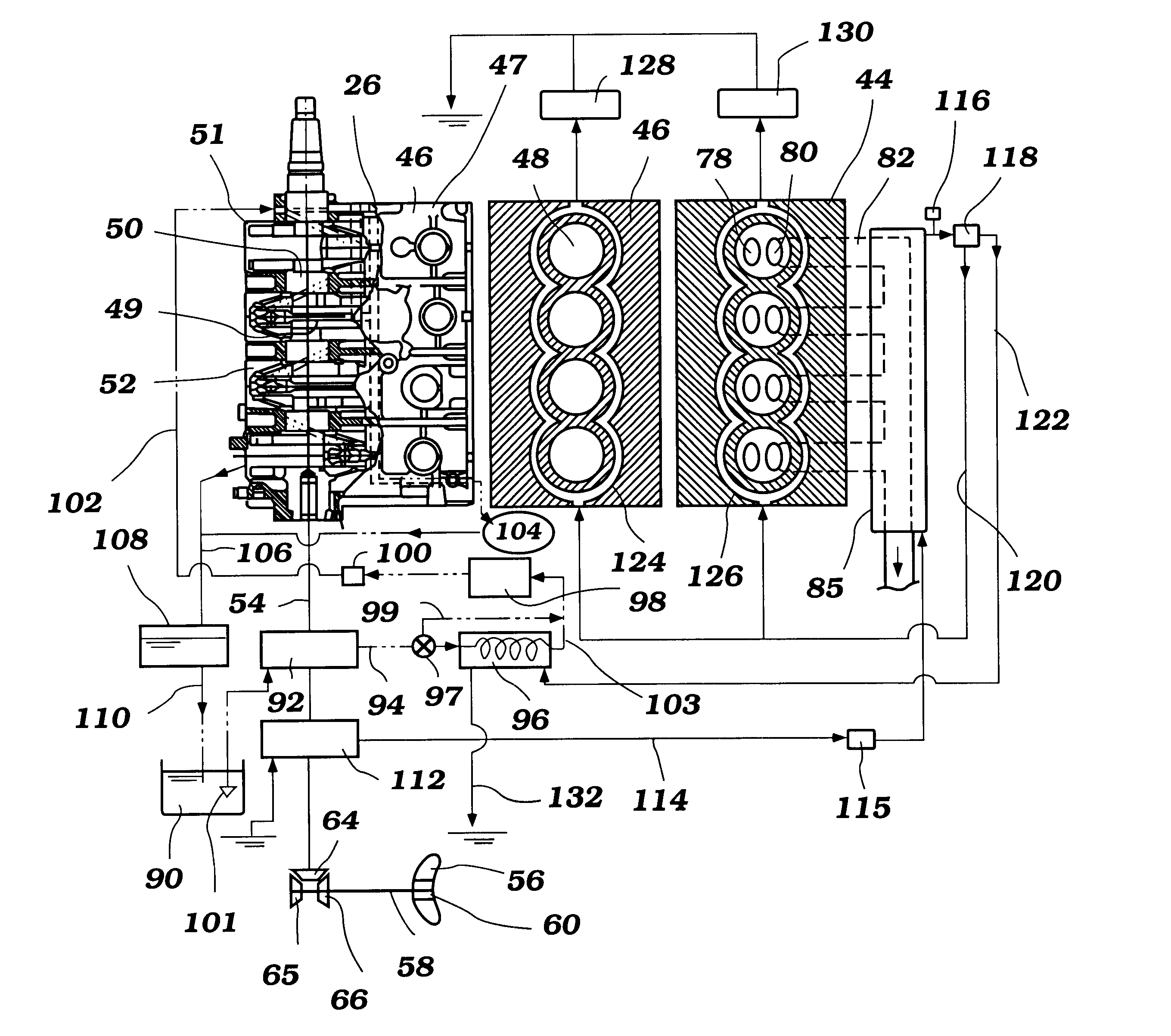
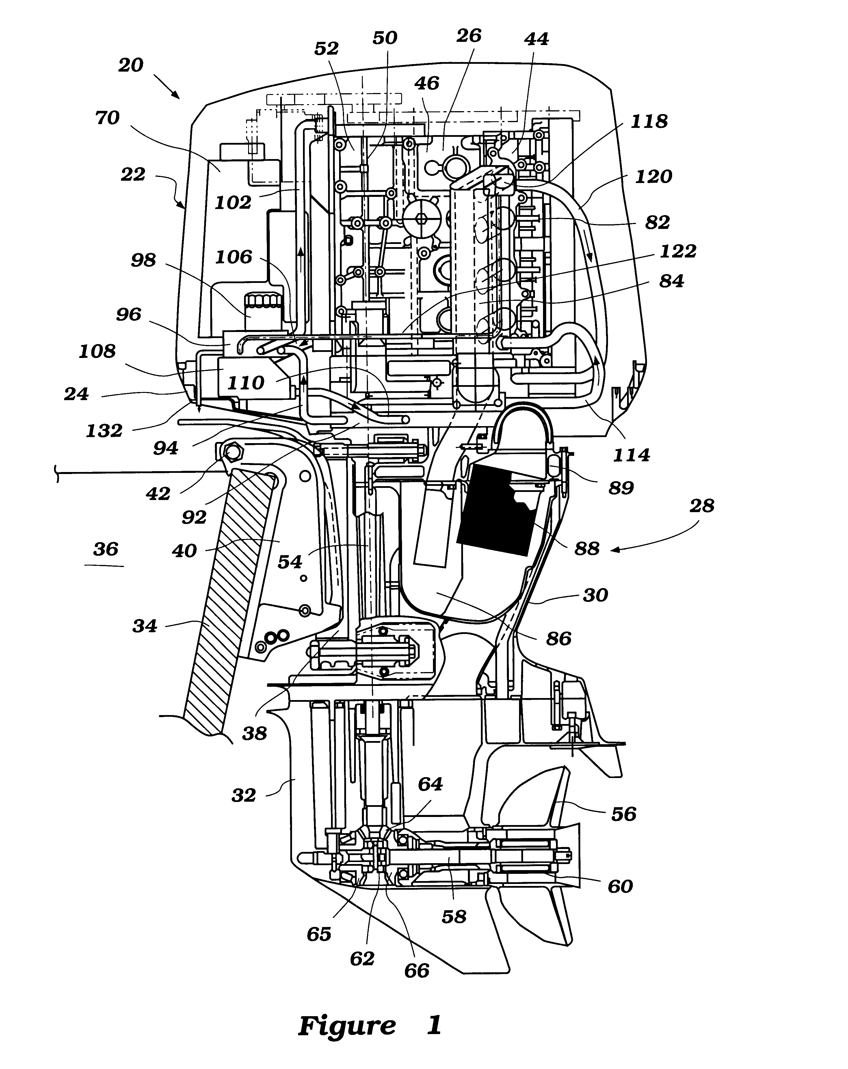
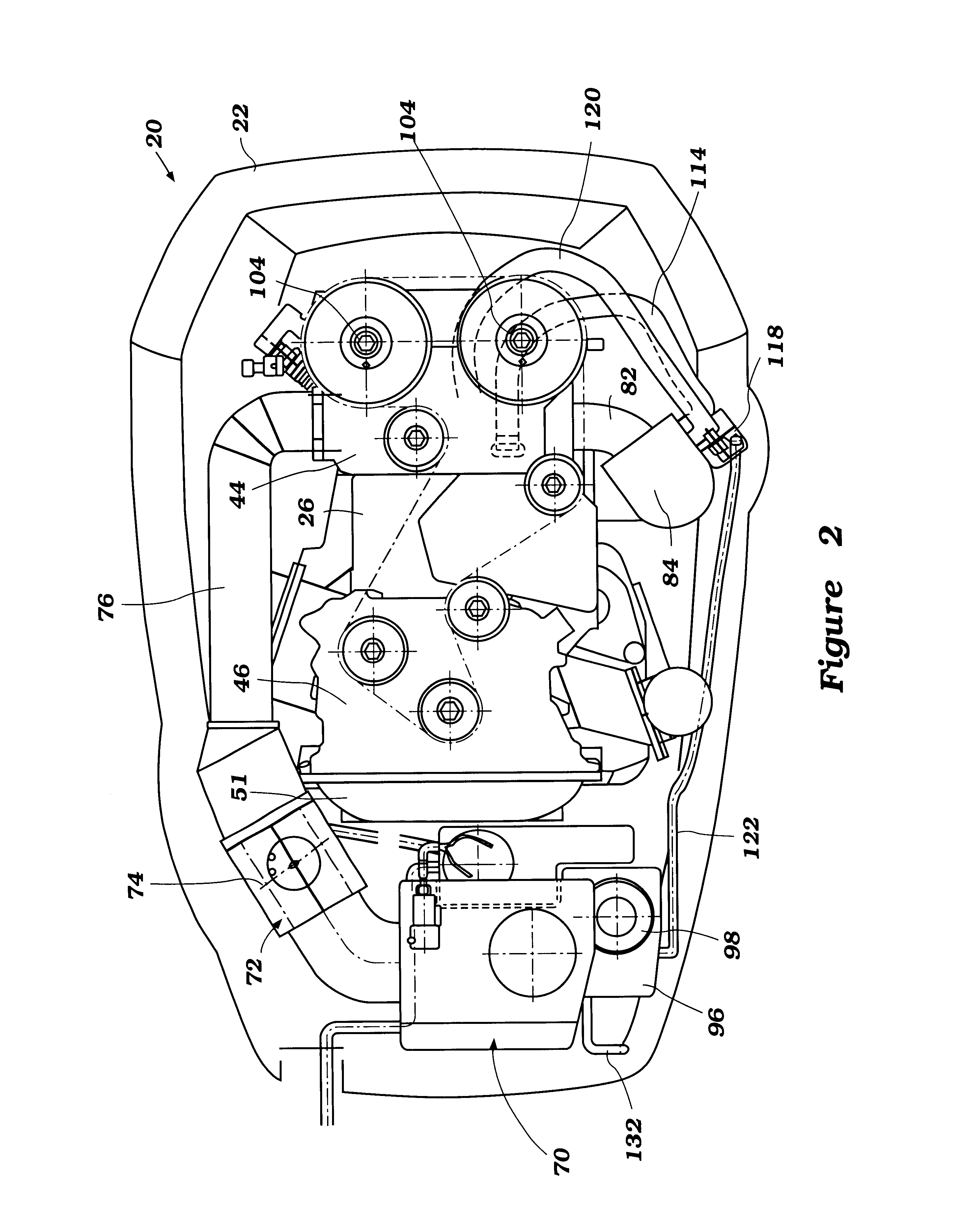
With initial reference to FIG. 1, an outboard motor, indicated generally by the reference numeral 20, having a lubricant cooling system is illustrated therein. The lubricant cooling system is preferably used to cool lubricant of a lubrication system of an internal combustion engine powering the outboard motor. The lubricant cooling system of the present invention will be described in conjunction with a lubrication system of an internal combustion engine of an outboard motor because this is an application for which the present system has particular utility. However, those of ordinary skill in the art will readily appreciate that the system may also have utility in a variety of other applications (i.e., with an inboard marine engine, automobile engine or snowmobile engine).

With continued reference to FIG. 1, the outboard motor 20 preferably includes a power head which generally comprises a main cowling 22 and a tray 24. The tray 24 supports the main cowling 22 in any suitable manner. ...


PUM


Abstract

An outboard motor contains a four-cycle engine. The engine includes a lubricant supply system that recirculates lubricant through the engine to lubricate the moving components of the internal combustion engine. The lubricant supply system includes a lubricant cooler. The lubricant cooler is selectively bypassed by lubricant and / or coolant to maintain the proper operating temperature range for the lubricant, depending upon the lubricant temperature and / or the coolant temperature.

Description

1. Field of the InventionThe present invention generally relates to lubricant supply systems for four-cycle internal combustion engines used in powering watercraft. More particularly, the present invention relates to cooling systems for the lubricant supply systems of such engines.2. Related ArtWatercraft are commonly powered by internal combustion engines contained within outboard motors. These motors have a water propulsion device, such as a propeller, which is driven by an output shaft of the internal combustion engine. The engine is also typically mounted within an enclosed cowling of the motor.As is well known to those of ordinary skill in the art, internal combustion engines, particularly four-cycle internal combustion engines, require lubricant that is supplied to a crank chamber and other moving components of the engine by a lubricant pump. In general, the lubricant circulates between a crank chamber of the engines and a lubricant pan associated with the engines. These lubri...

Claims


Application Information

Patent Timeline
IPC IPC(8): F01M5/00F02B75/20F01P7/16F02B75/00F01P7/14F02B61/00F02B61/04F01P3/02F02B75/18F01M1/16B63H20/00F01P11/08
CPCF01M5/005F01M5/007F01P7/16F02B61/045F02B75/20F01P2003/021F01P2003/024F01P2003/028F01P2025/40F01P2050/04F01P2060/04F02B2075/1816
Inventor OKAMOTO, YUTAKA
Owner SANSHIN KOGYO CO LTD
Learn More