Liquid metal thermal interface material system

Inactive Publication Date: 2008-06-12
MACRIS CHRIS G +2
View PDF7 Cites 54 Cited by
  • Summary
  • Abstract
  • Description
  • Claims
  • Application Information

AI Technical Summary

Benefits of technology

[0039]Accordingly, it is the overall feature of the present invention to provide an improved thermal interface sys

Problems solved by technology

Failure to effectively conduct away heat leaves these devices at high operating temperatures, ultimately resulting in decreased performance and reliability and ultimately failure.
Most liquids do not, however, have very high conductivity.
Typical problems with greases include to pumping and dry out, both of which can cause the conducting medium to lose contact with one or both of the heat transfer surfaces.
Although liquid metal alloys offer both low interfacial resistance and high conductivity, they have historically suffered from various reliability issues including corrosion/oxidation, intermetallic formation, drip-out, dewetting, and migration.
Unless mitigated, these mechanisms will continue to degrade the interface, resulting in a thermally related catastrophic

Method used


Image

  • Liquid metal thermal interface material system
  • Liquid metal thermal interface material system
  • Liquid metal thermal interface material system

Examples


Embodiment Construction

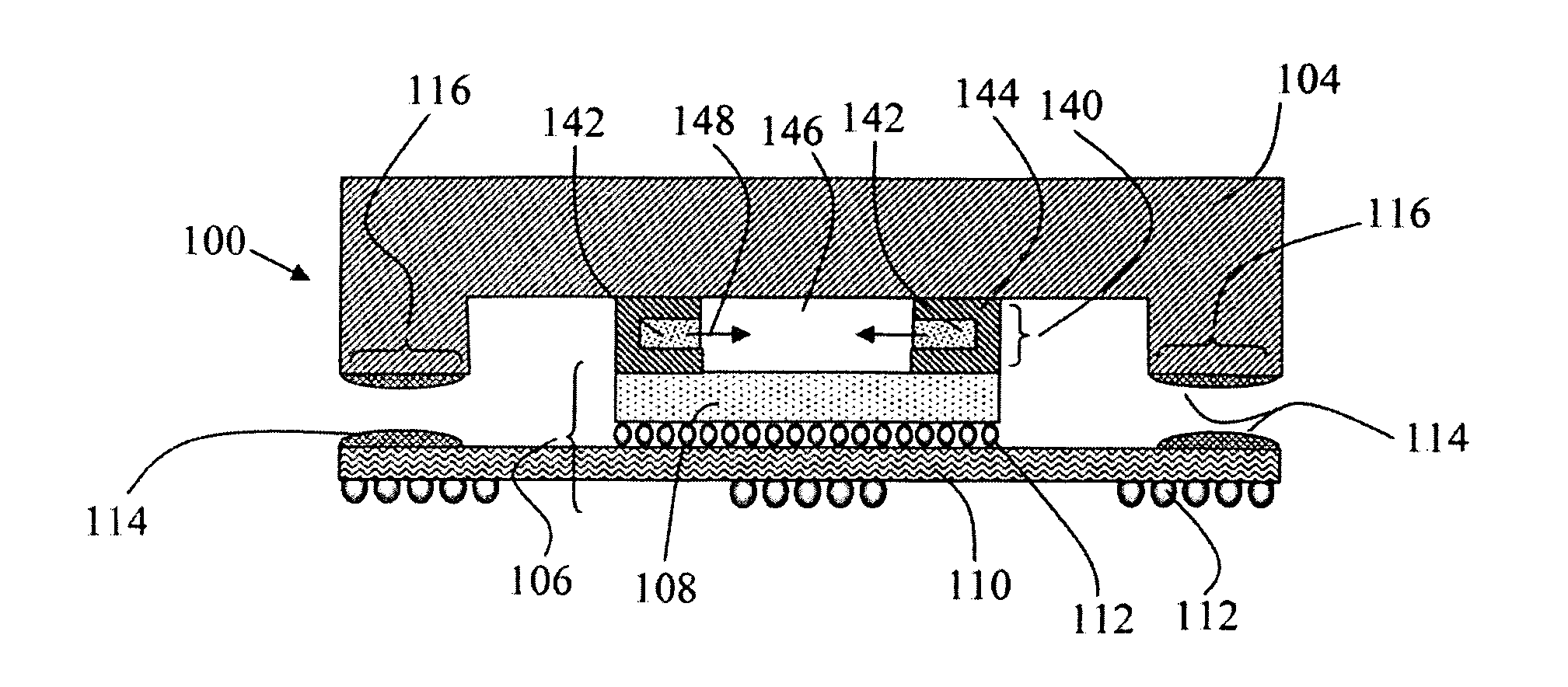
[0063]FIGS. 4a through 4d illustrate a sequence of the present invention in which the thermal interface structure 140 flows and fills the space between the electronic component and heat exchanger to yield a highly conductive and hermetic thermal interface joint. An electronic assembly 100 includes a heat exchanger 104 (depicted as a heat spreader lid), a thermal interface structure 140 positioned between the lid 104 and an electronic component 106. The component 106 is comprised of an IC chip 108, package substrate 110 and electrical interconnection vias 112 (on the chip 108 and substrate 110).

[0064]Within FIG. 4a, a thermal interface structure 140 includes a metallic seal member 142 (comprised of an inner and outer perimeter) which is positioned near the perimeter of the IC chip 108 and is comprised of a metallic interface composition. It can be seen that the metallic seal member 142 does not extend beyond the periphery of the IC chip 108. A coating layer 144 encapsulates the metal...


PUM

PropertyMeasurementUnit
Temperatureaaaaaaaaaa
Thicknessaaaaaaaaaa
Compositionaaaaaaaaaa

Abstract

A metal thermal interface structure for dissipating heat from electronic components comprised a heat spreader lid, metal alloy that is liquid over the operating temperature range of the electronic component, and design features to promote long-term reliability and high thermal performance.

Description

CROSS-REFERENCE TO RELATED APPLICATIONS[0001]The present application is a continuation-in-part of, and claims priority from, U.S. patent application Ser. No. 11 / 248,720 filed Oct. 11, 2005, and still pending.TECHNICAL FIELD[0002]This invention relates to the field of heat transfer structures between electronic components and their associated heat exchangers and, more particularly, to a thermal interface system which utilizes a metal alloy interface, materials and design features to stabilize the alloy while exposed to various environmental conditions.BACKGROUND OF THE INVENTION[0003]Today's electronic components generate significant amounts of heat which must be removed to maintain the component's junction temperature within safe operating limits. Failure to effectively conduct away heat leaves these devices at high operating temperatures, ultimately resulting in decreased performance and reliability and ultimately failure.[0004]The heat removal process involves heat conduction betw...

Claims


Application Information

Patent Timeline
IPC IPC(8): H05K7/20H01S4/00B21D53/02
CPCH01L23/10Y10T29/49002H01L23/433H01L24/32H01L2224/16225H01L2224/27013H01L2224/32057H01L2224/73204H01L2224/73253H01L2224/83051H01L2224/83385H01L2924/01003H01L2924/01005H01L2924/01011H01L2924/01012H01L2924/01013H01L2924/0102H01L2924/01029H01L2924/0103H01L2924/0104H01L2924/01049H01L2924/0105H01L2924/01057H01L2924/01058H01L2924/01059H01L2924/0106H01L2924/01063H01L2924/01064H01L2924/01073H01L2924/01082H01L2924/01105H01L2924/01327H01L2924/10158H01L2924/14H01L2924/15151H01L2924/15311H01L2924/16151H01L2924/16152H01L2924/3011H01L2924/3025H01L2924/01006H01L2924/01019H01L2924/01023H01L2924/01033H01L2924/01041H01L2924/01065H01L2924/01066H01L2924/0107H01L2924/01072H01L23/42Y10T29/4935H01L2924/3651H01L2924/3512H01L2924/00H01L2224/2612H01L2924/00011H01L2924/00014H01L2924/15787H01L2224/0401
Inventor MACRIS, CHRIS G.EBEL, ROBERT G.MCCULLOUGH, JOHN C.
Owner MACRIS CHRIS G
Why Eureka
Try Eureka