Liquid metal thermal interface material system

a thermal interface material and liquid metal technology, applied in the direction of semiconductor devices, semiconductor/solid-state device details, electrical devices, etc., can solve the problems of reducing performance and reliability, and affecting the effect of thermal energy transfer

Inactive Publication Date: 2006-06-08
MACRIS CHRIS +2
View PDF31 Cites 61 Cited by
  • Summary
  • Abstract
  • Description
  • Claims
  • Application Information

AI Technical Summary

Benefits of technology

[0032] Accordingly, it is the overall feature of the present invention to provide an improved thermal interface system in order to more effectively transfer thermal energy from an electronic component to a heat exchange structure.

Problems solved by technology

Failure to effectively conduct away heat leaves these devices at high operating temperatures, resulting in decreased performance and reliability and ultimately failure.
Most liquids do not, however, have very high conductivity.
Typical problems with greases include pumping and dry out, both of which can cause the conducting medium to lose contact with one or both of the heat transfer surfaces.
Although liquid metal alloys offer both low interfacial resistance and high conductivity, they have historically suffered from various reliability issues including corrosion / oxidation, intermetallic formation, drip-out, dewetting, and migration.
Unless mitigated, these mechanisms will continue to degrade the interface, resulting in a thermally related catastrophic failure of the actual electronic component.
The ability to contain an electrically conductive liquid within an electronic package presents significant challenges.
Although, these various mechanisms mitigate liquid metal migration, some disclosures include elastomeric or polymeric components in the thermal path which is thermally undesirable.
These elastomeric components are not hermetic and therefore do not prevent air or moisture from entering the thermal joint.
In addition, corrosion will propagate through the thermal interface should any air gaps be present.
Surface asperities of the heat source and heat exchanger increase the potential for voids.
Additionally, the holes 134 in the lid would also created undesirable thermal impedance between the chip 108 and lid 104.

Method used


Image

  • Liquid metal thermal interface material system
  • Liquid metal thermal interface material system
  • Liquid metal thermal interface material system

Examples


embodiment 147

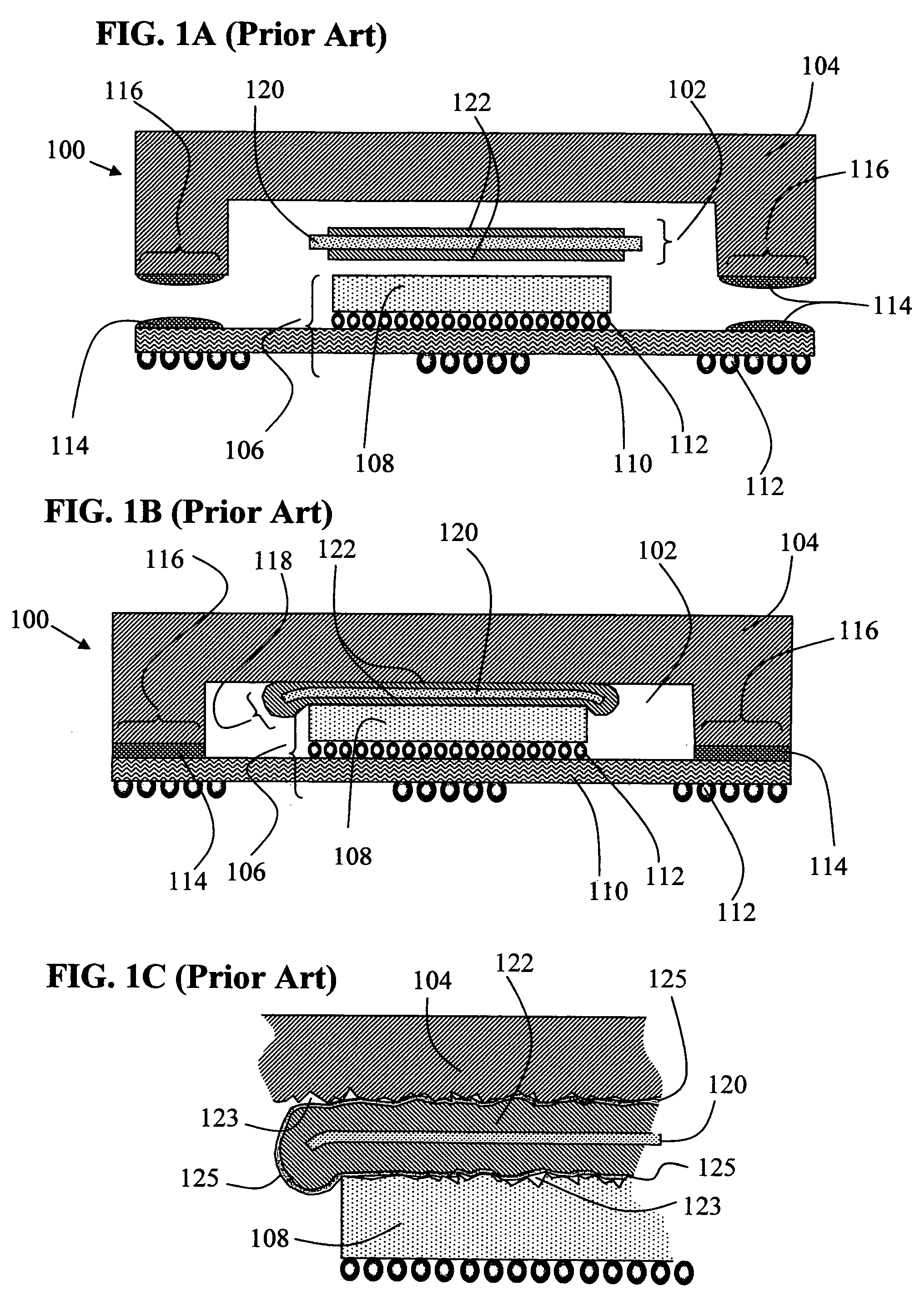
[0073]FIG. 11, similar to FIG. 10B, illustrates another thermal interface structure embodiment 147 wherein the metallic core 154 and coating layer 144 extends a distance from the outer perimeter of the metallic seal member 142, thereby forming a boundary region 152 which facilitates bonding of the individual coating layers as well as adhesive attachment to a variety of heat exchangers.

[0074] As seen in FIG. 12, a thermal interface structure 149 (similar to FIG. 11) is illustrated wherein the solid metallic core 154 includes a diffusion barrier layer 156 and wetting layer 158 (over the diffusion barrier layer). In one embodiment of the present invention, the metallic interface composition (comprising the metallic seal member 142) is applied to the solid metallic core 154 prior to melting of the metallic seal member 142 in order to further facilitate wetting and flowing of the metallic interface composition on the core 154.

[0075] Now, within FIG. 13, metallic interface composition “i...

embodiment 153

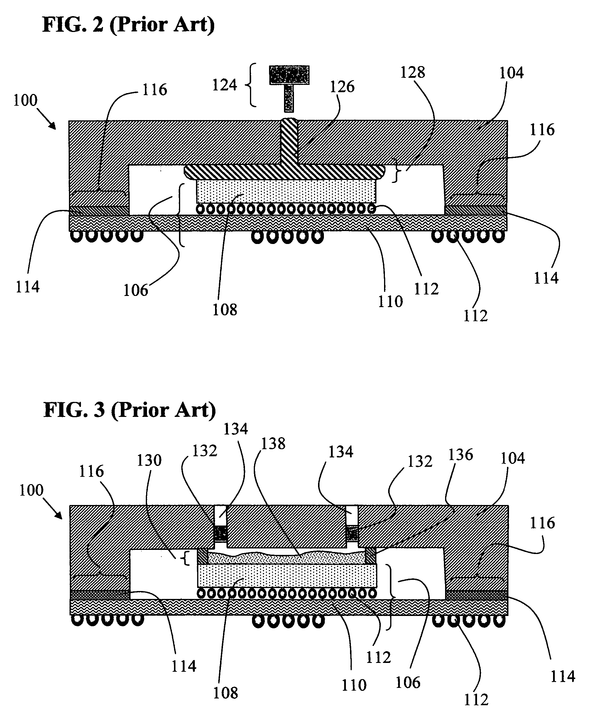
[0079] As seen in FIG. 15, another thermal interface structure embodiment 153 of the present invention, a boundary region 152, located outside of the outer perimeter of the metallic seal (illustrated as the space 146), includes an adhesive layer 166 which facilitates attachment of the interface structure 140 to the heat exchanger (lid 104).

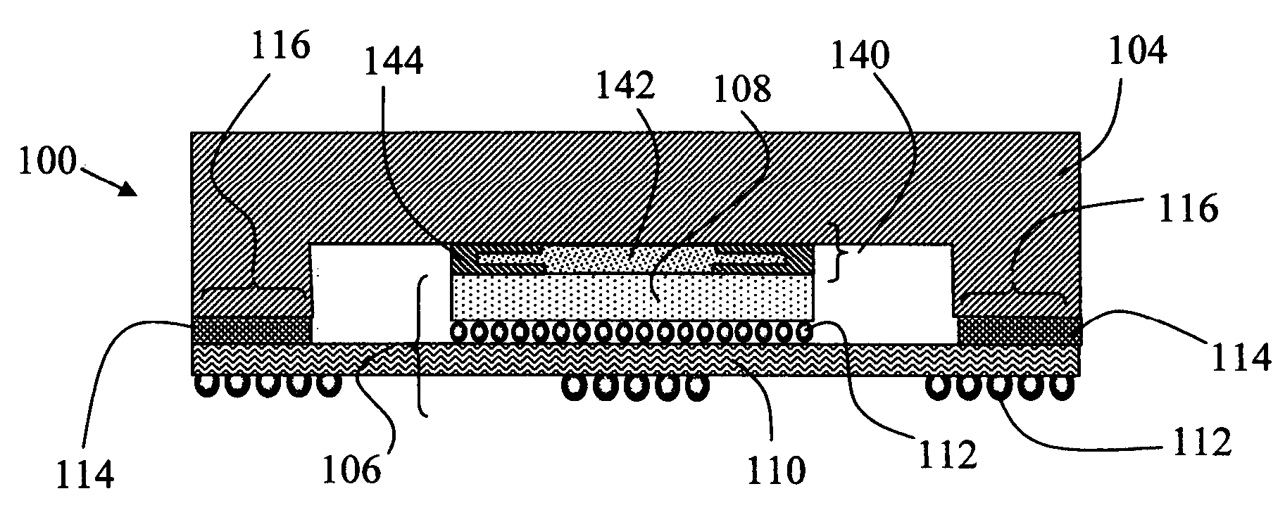
[0080]FIG. 16 illustrates an electronic assembly 170 including an electronic component 106 (comprised of an IC chip 108, package substrate 110, and electrical interconnection vias 112), heat exchanger (heat sink) 168, and thermal interface structure 172. The thermal interface structure 172 includes a metallic seal member (comprised of a metallic interface composition), illustrated as the space 146, coating layer 144, and facilitates a thermal path between the IC chip 108 and heat sink 168. As another embodiment of FIGS. 4A through 4D, FIG. 16 illustrates the thermal interface structure 172 after the metallic seal member has melted and flowed into ...


PUM

PropertyMeasurementUnit
metallicaaaaaaaaaa
perimeteraaaaaaaaaa
conductivityaaaaaaaaaa

Abstract

A metal thermal interface structure for dissipating heat from electronic components comprised a heat spreader lid, metal alloy that is liquid over the operating temperature range of the electronic component, and design features to promote long-term reliability and high thermal performance.

Description

[0001] The present application is a continuation-in-part of, and claims priority from, U.S. patent application Ser. No. 11 / 004,107, filed Dec. 3, 2004, and still pending.TECHNICAL FIELD [0002] This invention relates to the field of heat transfer structures between electronic components and their associated heat exchangers and, more particularly, to a thermal interface system which utilizes a metal alloy interface, materials and design features to stabilize the alloy while exposed to various environmental conditions. BACKGROUND OF THE INVENTION [0003] Today's electronic components generate significant amounts of heat which must be removed to maintain the component's junction temperature within safe operating limits. Failure to effectively conduct away heat leaves these devices at high operating temperatures, resulting in decreased performance and reliability and ultimately failure. [0004] The heat removal process involves heat conduction between the electronic component and heat exch...

Claims


Application Information

Patent Timeline
Patent Type & Authority Applications(United States)
IPC IPC(8): H01L23/495
CPCH01L23/055H01L2924/3651H01L23/26H01L23/42H01L23/433H01L24/28H01L24/31H01L2224/16225H01L2224/27013H01L2224/73204H01L2224/73253H01L2224/83051H01L2924/01003H01L2924/01005H01L2924/01011H01L2924/01012H01L2924/01013H01L2924/0102H01L2924/01029H01L2924/0103H01L2924/0104H01L2924/01049H01L2924/0105H01L2924/01057H01L2924/01058H01L2924/01059H01L2924/01063H01L2924/01064H01L2924/01073H01L2924/01105H01L2924/01327H01L2924/10158H01L2924/14H01L2924/15311H01L2924/16151H01L2924/16152H01L2924/3011H01L2924/3025H01L2924/01006H01L2924/01019H01L2924/01023H01L2924/01033H01L2924/01041H01L2924/01065H01L2924/01066H01L2924/0107H01L2924/01072H01L23/10H01L2924/00014H01L2924/00011H01L2224/0401
Inventor MACRIS, CHRISSANDERSON, THOMAS R.EBEL, ROBERT G.
Owner MACRIS CHRIS
Why Eureka
Try Eureka