
Magnetic recording medium

a recording medium and magnetic technology, applied in the field of magnetic recording mediums, can solve the problems of inadvertent rewriting or erasure of servo information when, degradation of read signals becomes a problem,

Inactive Publication Date: 2002-07-16
TDK CORPARATION
View PDF5 Cites 56 Cited by
  • Summary
  • Abstract
  • Description
  • Claims
  • Application Information

AI Technical Summary

Benefits of technology

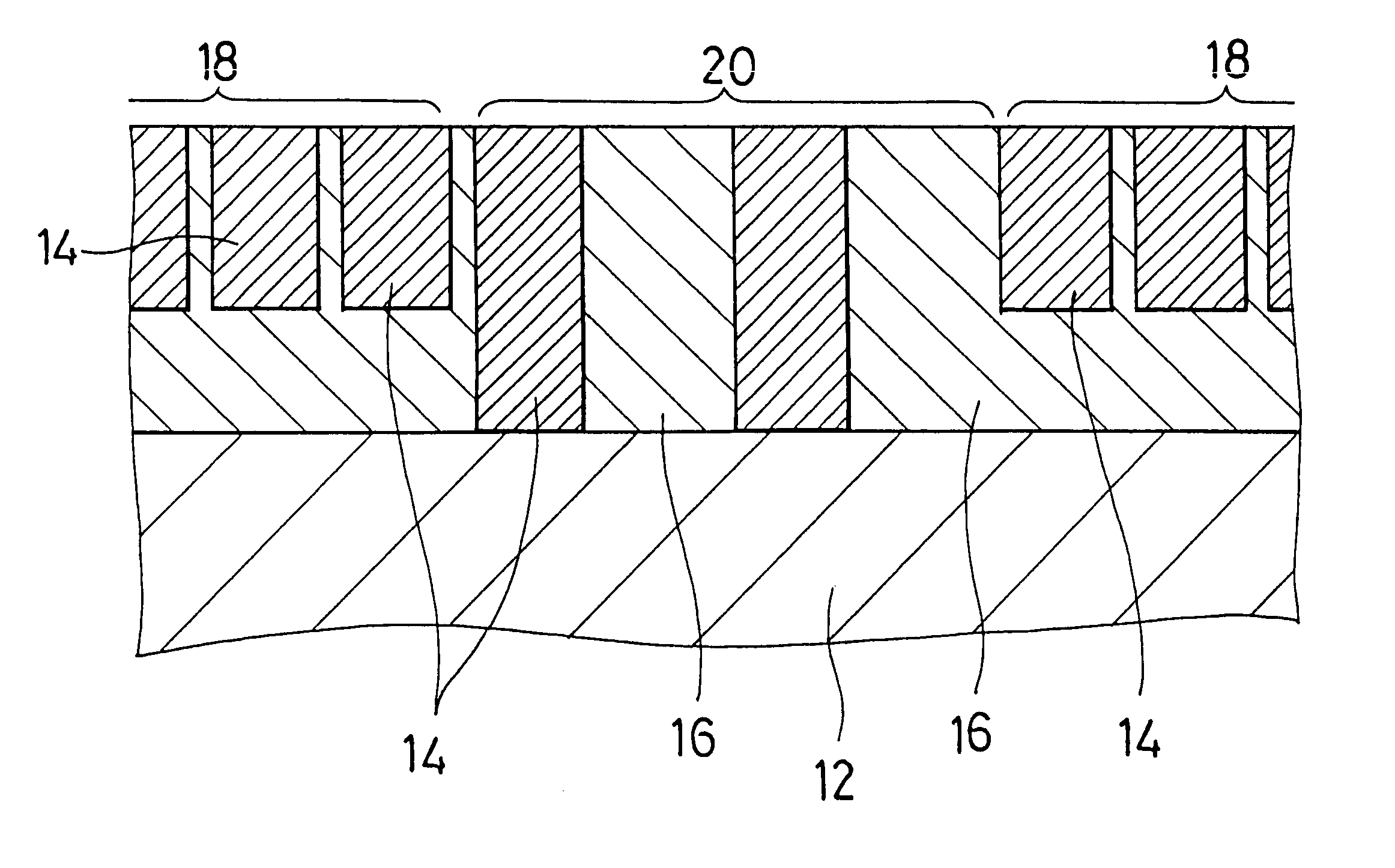
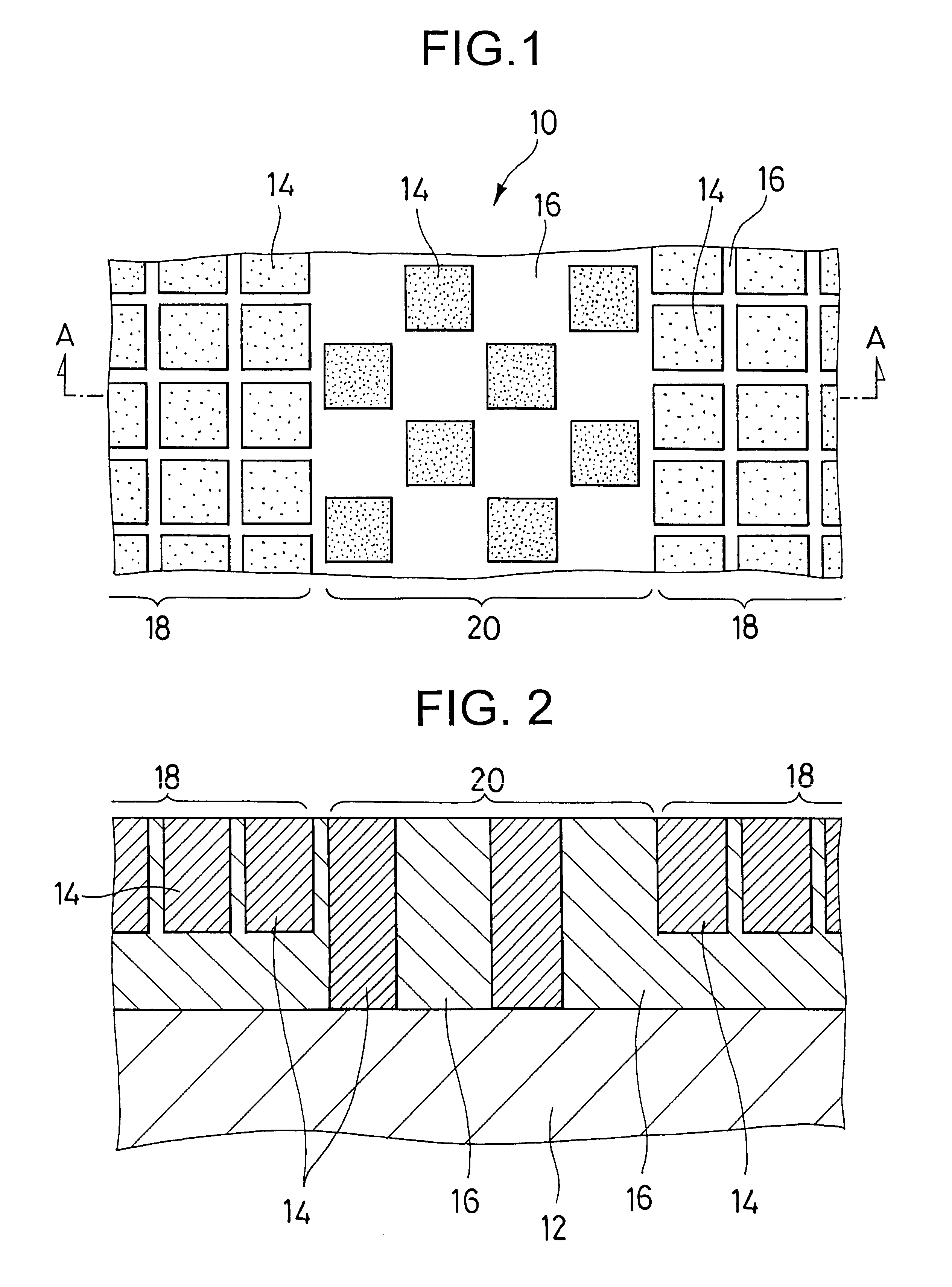
According to the invention, the aspect ratio in the servo regions is set at least 1.5 times the aspect ratio in the data regions. With this setting, the unit minute recording portions in the servo regions have a sufficiently high coercivity as compared with those in the data regions. This prevents erasure of servo information even when a record erasing magnetic field to be applied to only the data region is inadvertently applied to the servo region, when the magnetic recording medium is re-formatted, or when the recorded data in the data region is erased by an external magnetic field other than the record erasing magnetic field.

Problems solved by technology

However, if the track width is too narrow, the interference or crosstalk between magnetic signals from adjacent recording tracks increases so that the degradation of read signals becomes a problem.
If the recording bit length is too short, the interference or partial erasure between magnetic signals from adjacent bits increases so that the degradation of read signals becomes a problem.
However, it was not discussed in the prior art how to record servo information in a patterned medium of the perpendicular recording type.
In that event, however, there arises a problem that servo information can be inadvertently rewritten or erased when data are recorded or erased.
However, if AR.sub.S / AR.sub.D is too high, the coercivity becomes too high in the servo regions, making it difficult to record the servo information.
Also the aspect ratio becomes too high in the servo regions, and as a result, it becomes difficult to form the unit minute recording portions in the servo regions.
Further, if the aspect ratio becomes higher than a certain value, no further improvement in coercivity is obtained.
Also, if AR.sub.D is too high, the coercivity becomes too high in the data regions, making it difficult to rewrite the information.
However, if AR.sub.D is too low, magnetic recording in the data regions becomes less stable.

Method used


Image

  • Magnetic recording medium
  • Magnetic recording medium
  • Magnetic recording medium

Examples


Embodiment Construction

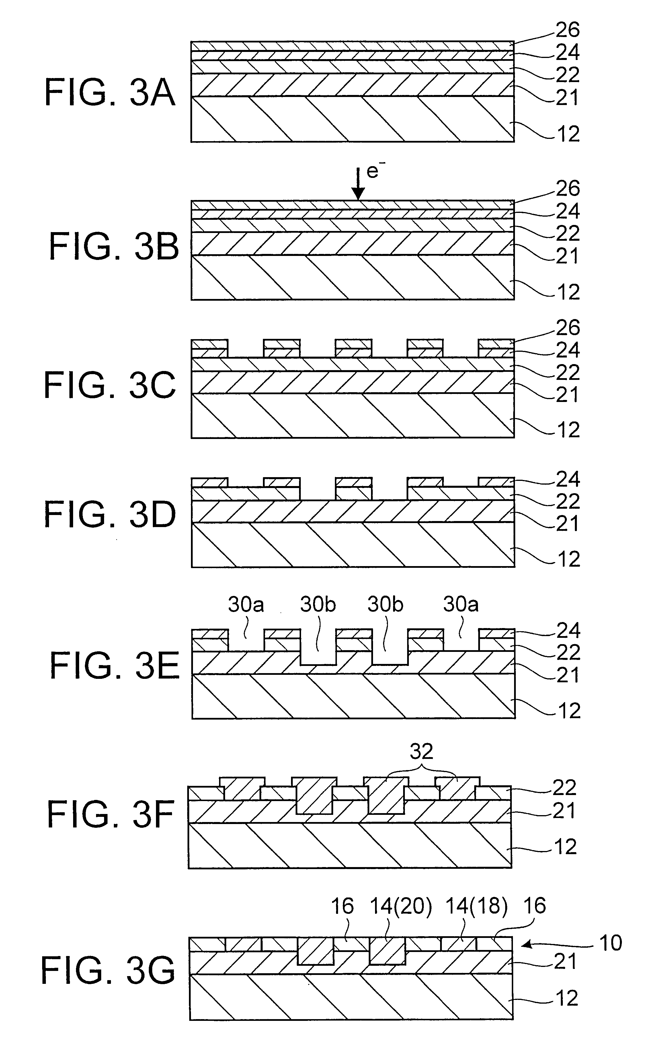
Magnetic disk medium samples as shown in Table 1 were prepared by the method shown in FIGS. 4A to 4G. The unit minute recording portions were constructed of cobalt and the non-recording portions were constructed of silicon dioxide (SiO.sub.2). The surface shape of unit minute recording portions was square. In each sample, this square has a side length L as shown in Table 1. The array pitch of unit minute recording portions was equal to 2L in both longitudinal and transverse directions of a recording track. It is noted that L=56 nm corresponds to a recording density of 50 Gb / in.sup.2, L=40 nm corresponds to a recording density of 100 Gb / in.sup.2, and L=28 nm corresponds to a recording density of 200 Gb / in.sup.2. For each sample, the aspect ration AR.sub.D in the data region, the aspect ratio AR.sub.S in the servo region, and AR.sub.S / AR.sub.D are reported in Table 1.

For these samples, the coercivity Hc of a unit minute recording portion in each of the data and servo regions is shown...


PUM


Abstract

The invention aims to prevent inadvertent rewriting or erasure of servo information in a patterned medium based on the perpendicular recording mode. The magnetic recording medium of the invention includes recording tracks each having an array of unit minute recording portions of a magnetic material separated by non-recording portions of a nonmagnetic material. The recording tracks include data regions and servo regions. The unit minute recording portions in the data regions have substantially the same surface area as the unit minute recording portions in the servo regions. The invention satisfies ARS / ARD>=1.5 provided that the unit minute recording portion has an aspect ratio which is the thickness divided by the square root of the surface area, the unit minute recording portion in the data region has an aspect ratio ARD, and the unit minute recording portion in the servo region has an aspect ratio ARS.

Description

1. Technical FieldThis invention relates to a magnetic recording medium, more particularly, to a magnetic recording medium for use in magnetic read / write equipment such as magnetic disk equipment known as hard disk drives (HDD), and further particularly, to the structure of a magnetic recording medium of the perpendicular recording type having a high recording density.2. Background ArtHigh-capacity storage devices, especially hard disk drives featuring a high data transfer rate, quick access, high reliability and low price have marked a significant advance toward higher capacity and higher density. An improvement in areal recording density is accomplished by miniaturizing recording magnetic domains formed in the magnetic recording layer. At present, the density has exceeded 5 gigabits per square inch, with development efforts being made with the target on 10 gigabits to 100 gigabits.Used as the magnetic head for write and read operation is a combined magnetic head in which an induct...

Claims


Application Information

Patent Timeline
IPC IPC(8): G11B5/72G11B5/855
CPCG11B5/72G11B5/855Y10T428/265Y10T428/2495Y10S428/90G11B5/716
Inventor HARATANI, SUSUMUAOYAMA, TSUTOMU
Owner TDK CORPARATION
Learn More