Method for monitoring alternating current discharge on a double electrode and apparatus

a technology of alternating current and double electrodes, applied in the direction of electrical equipment, instruments, plasma techniques, etc., can solve the problems of frequent unnecessarily disruptive interruption of the energy supply of the discharge device, increased danger of forming an arc discharge on the respective target, and local overheating on the electrode surfa

Inactive Publication Date: 2002-07-16
HUETTINGER ELECTRONICS GMBH & CO KG
View PDF14 Cites 72 Cited by
  • Summary
  • Abstract
  • Description
  • Claims
  • Application Information

AI Technical Summary

Problems solved by technology

The problem in operating an alternating-voltage discharge on a double electrode with an alternating-current generator is that, in the case of the often very high electrical power used in practice, the discharge must continuously lie in the area of the anomalous glow discharge.
As a result, the danger of forming an arc discharge on the respective target increases.
The causes of a change-over of the discharge from an anomalous glow discharge to an arc discharge are diverse and cannot be completely excluded in practical operation.
Thus, the causes of malfunctions could lie, for example, in the formation of flakes of sputtered material that flake off device parts and/or cause local overheating on the electrode surfaces.
In this connection, it is problematic that, in the case of high power with frequencies of 10 to 80 kHz, various misinterpr

Method used


Image

  • Method for monitoring alternating current discharge on a double electrode and apparatus
  • Method for monitoring alternating current discharge on a double electrode and apparatus
  • Method for monitoring alternating current discharge on a double electrode and apparatus

Examples


Embodiment Construction

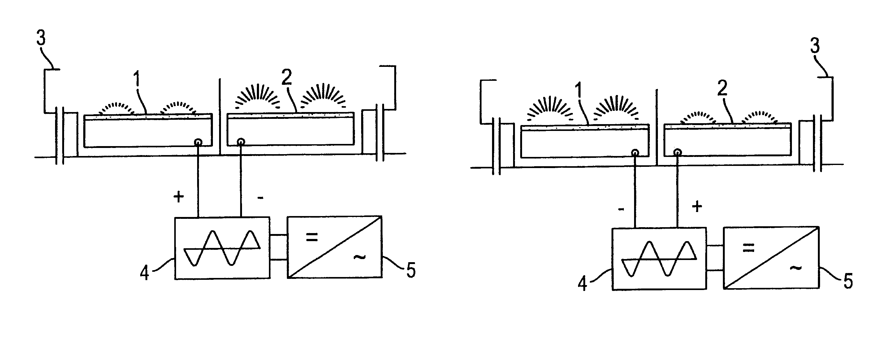
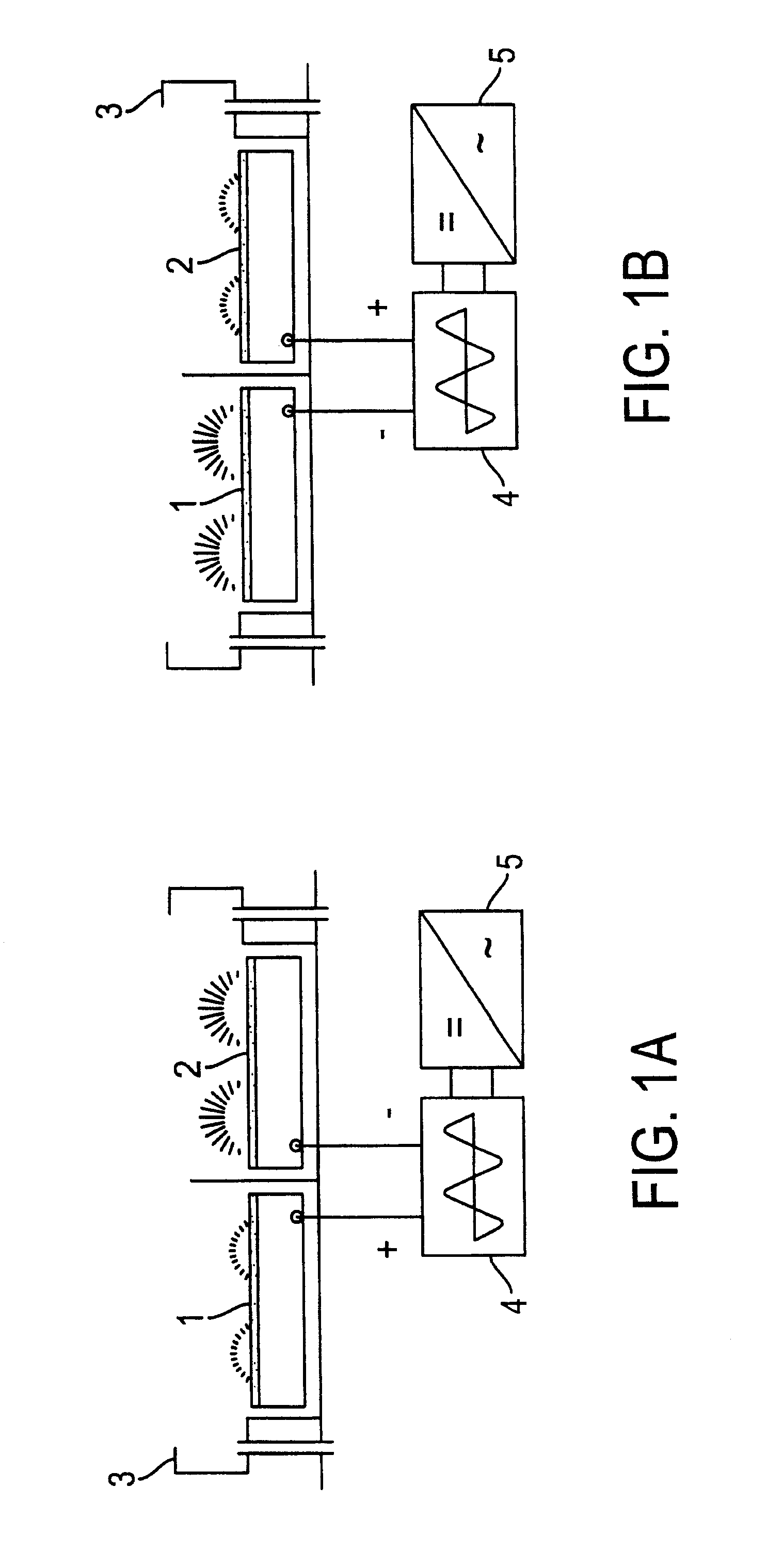
The same double magnetron is shown in FIGS. 1a and 1b, in which a target 1 and a target 2 electrically form the double electrode. With respect to the additional embodiments, FIG. 1a represents the relationships for a first half-wave of the discharge and FIG. 1b represents the following half-wave within a period of the alternating current.

The targets 1 and 2 are arranged in a housing-like sheathing 3 and are shielded against one another. The targets 1 and 2 are attached to a switching unit 4 outside the sheathing 3 as well as outside the coating chamber. The switching unit realizes the pole reversal between cathodic and anodic potential. The switching unit 4 is connected electrically directly with a power supply unit 5.

The devices to record the actual discharge current, the discharge voltage, and the actual duration of the individual half-waves are not shown in greater detail. The measuring elements for the discharge current and discharge voltage are located in the power supply unit ...


PUM


Abstract

Process for monitoring an alternating-voltage discharge between the electrodes of a double electrode and an apparatus. The process includes measuring values of at least one of a discharge current and a discharge voltage for each half-wave within an alternating-voltage discharge period, determining a difference between the measured values of a second half-wave and the measured values of the first half-wave, and comparing the determined differences to specific tolerance values. When the specific tolerance values are exceeded by the determined differences, a power supply is reduced, whereby the discharge is at least briefly suppressed. The apparatus includes a double magnetron including first and second targets arranged to form a double electrode, and a power supply coupled to supply power to the first and second targets. The power supply includes a measurement unit for measuring values of at least one of discharge current and discharge voltage, such that at least one of a discharge current and a discharge voltage for each half-wave within an alternating-voltage discharge period is measured. A device for determining a difference between the measured values of a second half-wave and the measured values of the first half-wave is provided, as well as a device for comparing the determined differences to specific tolerance values, and a device for at least briefly suppressing the discharge when the specific tolerance values are exceeded by the determined differences.

Description

1. Field of the InventionThe invention relates to a method for monitoring an alternating-voltage discharge on a double electrode, especially between two targets for cathodic sputtering. The method is used to avoid a change-over of the discharge from the state of the anomalous glow discharge to an arc discharge.2. Discussion of Background InformationIn this connection, the double electrode is basically an arrangement for an alternating-voltage discharge between two individual electrodes. The individual electrodes are placed alternatingly on cathodic and anodic potential. The method-related use of the alternating-voltage discharge can serve different purposes. On the one hand, the parameters and the electrode materials can be selected in such a way that essentially the plasma being formed with the discharge is used technically. On the other hand, the parameters and the electrode materials used can be selected in such a way that these materials are always sputtered on the cathodic side...

Claims


Application Information

Patent Timeline
IPC IPC(8): H01J37/32H01J37/34H05H1/00
CPCH01J37/3405H01J37/3444H05H1/0081
Inventor MILDE, FALKWINKLER, TORSTENFICKERT, ANDREASKIRCHHOFF, VOLKERFAHLAND, MATTHIAS
Owner HUETTINGER ELECTRONICS GMBH & CO KG
Why Eureka
Try Eureka