Optical switch

a technology of optical switches and mirror finishes, applied in the field of optical switches, can solve the problems of large optical loss, unsuitable mass production of optical switches, poor yield of mirror finishes,

Inactive Publication Date: 2002-07-16
MIMAKI ELECTRONICS COMPONENT
View PDF12 Cites 8 Cited by
  • Summary
  • Abstract
  • Description
  • Claims
  • Application Information

AI Technical Summary

Problems solved by technology

However, the configuration of communication circuits is such that 2.times.2 optical switches are required.
This can be implemented in practice using an optical branch circuit and two 1.times.2 optical switches, but an optical switching unit containing a large number of optical switches implemented in this way ends up being physically large and having a large optical loss due to the optical branch circuits.
An optical switch with such a construction is unsuited to mass production and would therefore be expensive.
Moreover, the fabrication step of producing a mirror finish has a poor yield, and this is another reason why such a component wou

Method used


Image

  • Optical switch
  • Optical switch
  • Optical switch

Examples


first embodiment

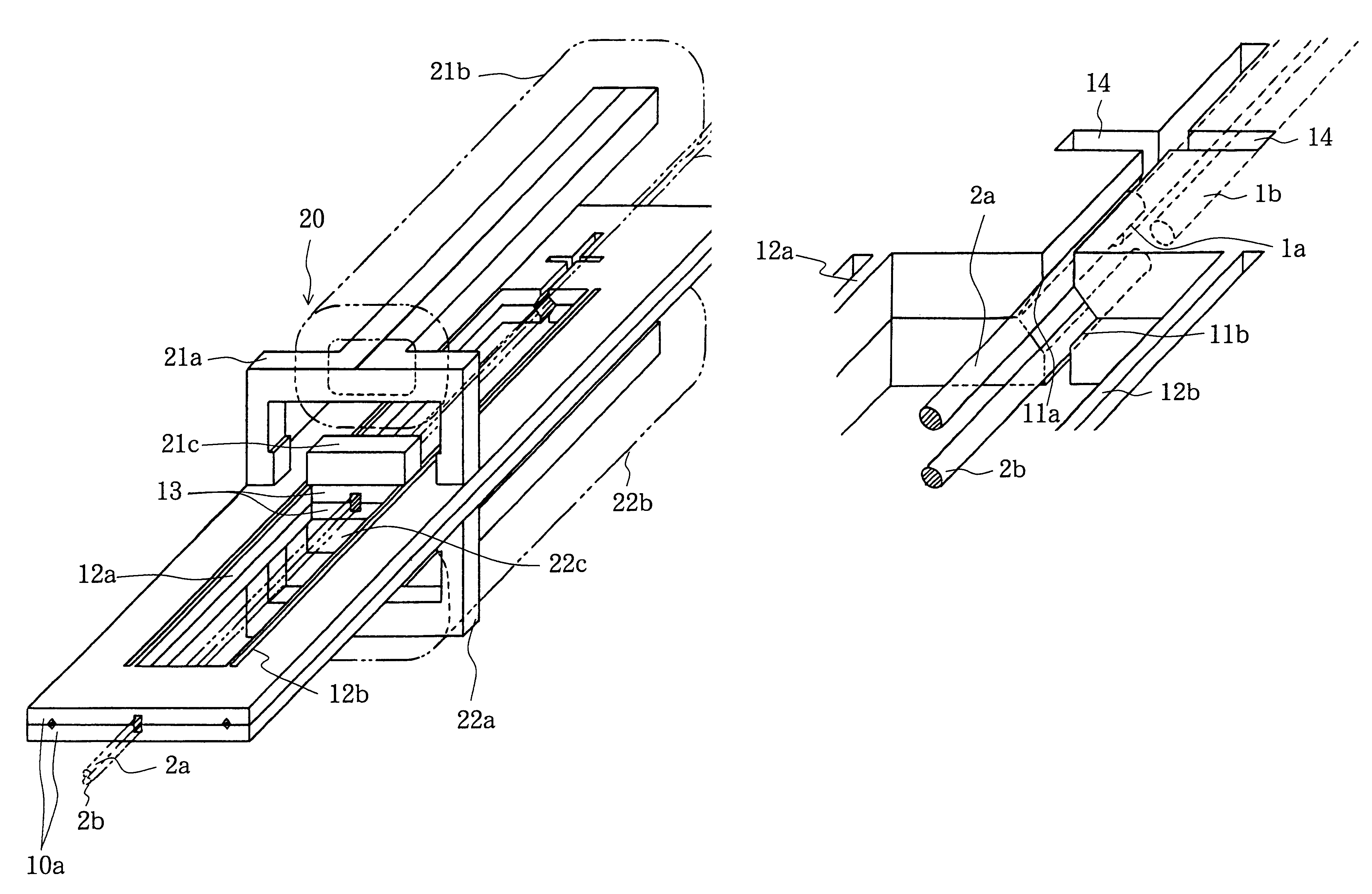
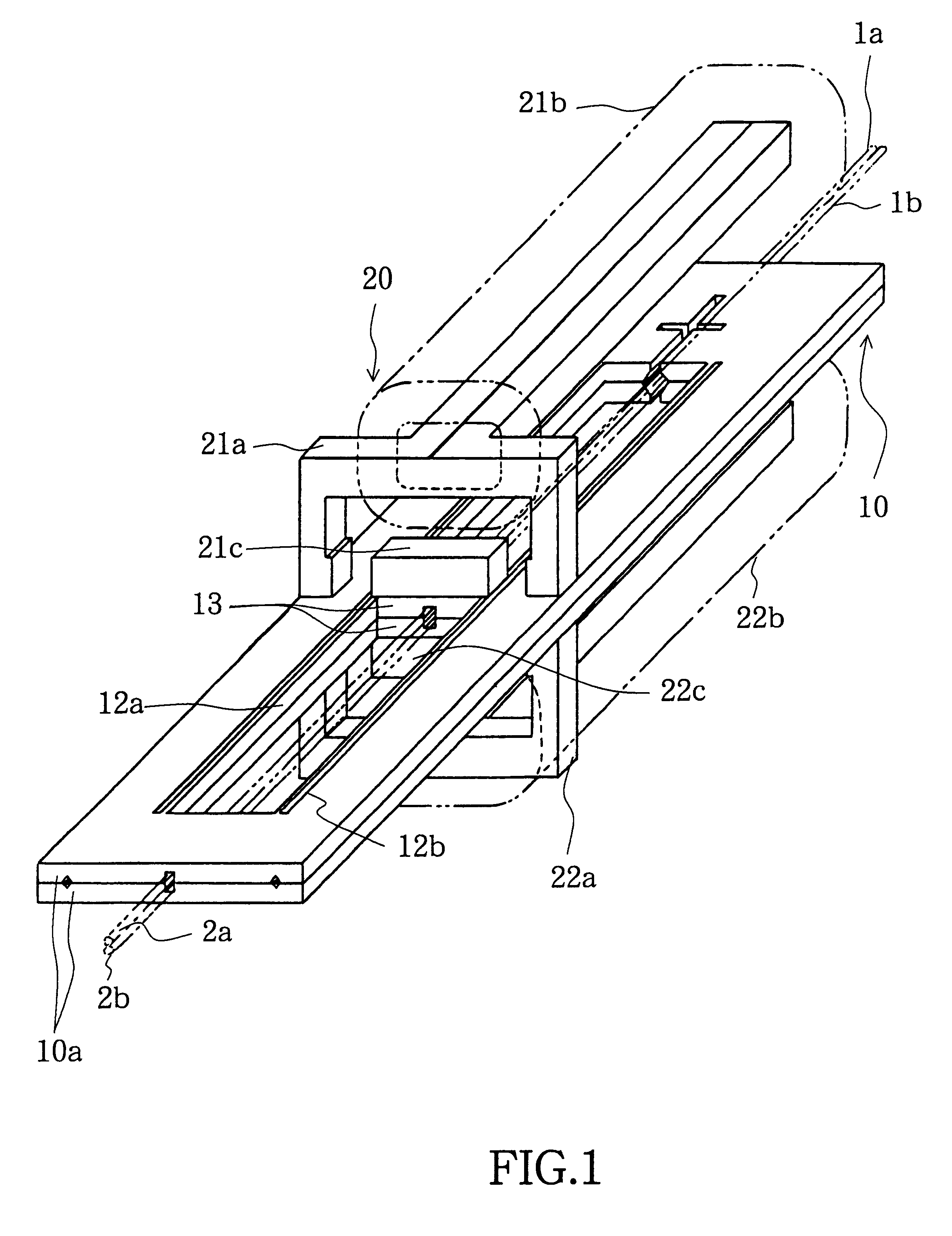
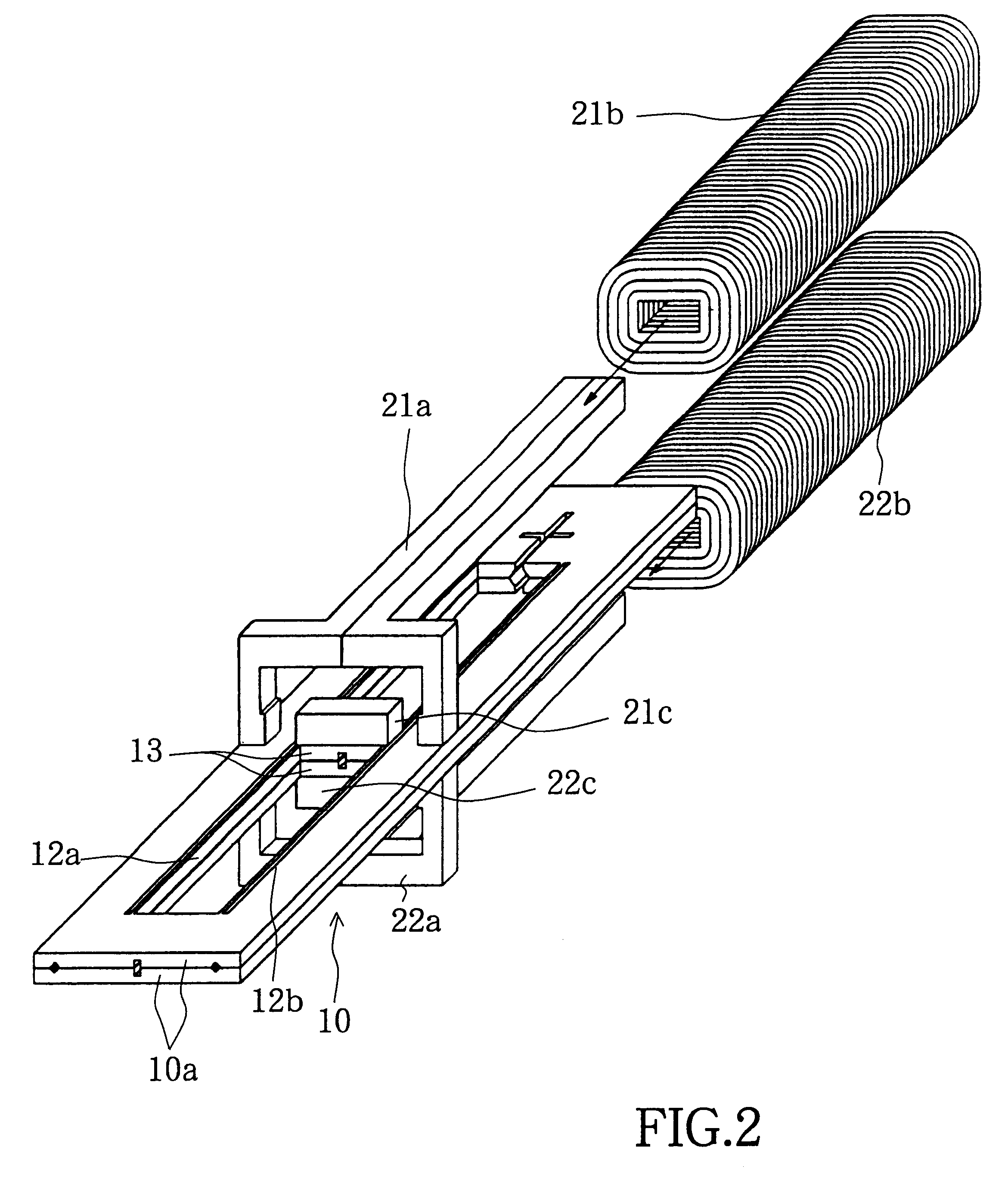
FIG. 1 is an enlarged perspective view showing the configuration of a first embodiment of this invention, and FIG. 2 is an enlarged exploded perspective view of the same. This first embodiment comprises a pair of fixed optical fibers 1a and 1b, a pair of movable optical fibers 2a and 2b, support member 10 for supporting the end portions of these fixed optical fibers and movable optical fibers, and drive mechanism 20 mounted on this support member and serving to produce a mechanical displacement of the end portions of the pair of movable optical fibers 2a and 2b.

FIG. 3 is an enlarged perspective view showing the shape of the support member in the first embodiment; FIG. 4 is an enlarged perspective view of portion A in FIG. 3 and showing optical fibers mounted in the support member in the first embodiment; and FIG. 5 is an enlarged interior plan view of FIG. 4 and showing optical fibers mounted in the support member in the first embodiment.

A pair of V-grooves 11a and 11b arranged with...

second embodiment

This second embodiment comprises a pair of fixed optical fibers 1a and 1b, a pair of movable optical fibers 2a and 2b, support member 10 for supporting the end portions of these fixed optical fibers and movable optical fibers, and drive mechanism 30 mounted on this support member and serving to produce a mechanical displacement of the end portions of the pair of movable optical fibers 2a and 2b.

As in the first embodiment, support member 10 is formed by sticking together two frames 10a. The pair of fixed optical fibers 1a and 1b and the pair of movable optical fibers 2a and 2b are fixed in the same manner as in the first embodiment.

Drive mechanism 30 comprises first electromagnetic means and second electromagnetic means. The first electromagnetic means comprises first core 31a, first coil 31b, first permanent magnet 31c fixed to linking portion 13 of upper frame 10a, and first covering plate 31d for covering the top of support member 10. Guiding groove 33 is formed in first covering ...

third embodiment

FIG. 31 is an enlarged perspective view showing the configuration of a third embodiment of this invention. This third embodiment comprises a pair of fixed optical fibers 1a and 1b, a pair of movable optical fibers 2a and 2b, support member 10 for supporting the end portions of these fixed optical fibers and movable optical fibers, and drive mechanism 40 mounted on this support member and serving to produce a mechanical displacement of the end portions of the pair of movable optical fibers 2a and 2b. As in the first embodiment, support member 10 is formed by sticking together two frames 10a. The pair of fixed optical fibers 1a and 1b and the pair of movable optical fibers 2a and 2b are fixed in the same manner as in the first embodiment.

Drive mechanism 40 comprises first electromagnetic means and second electromagnetic means. The first electromagnetic means comprises first core 41a, first coil 41b, and first permanent magnet 41c fixed to linking portion 13 of upper frame 10a. The sec...


PUM


Abstract

To make an optical switch smaller, two frames are formed by etching in such manner that when they are stuck together to form a support member, an hexagonal opening appears. The end portions of a pair of fixed optical fibers are arranged in the bottom portions of a pair of opposing V-grooves provided in this hexagonal opening. A pair of movable optical fibers are fixed at the other end of the support member, and these movable optical fibers are arranged in such manner that their end faces are contiguous with the end faces of the pair of fixed optical fibers. A drive mechanism causes the end portions of this pair of vertically arranged movable optical fibers to move to the left or the right, come into contact with the walls of respective V-grooves, slide into the bottoms of the grooves, and thereby have their cores aligned with the cores of the fixed optical fibers. Alternatively, two parallel beams formed from silicon are formed on the inside of a single frame, a pair of mutually opposing projections are formed in approximately the middle portions of these beams, and the end portions of a pair of optical fibers are arranged in and in contact with V-grooves formed parallel to and on the opposing faces of this pair of projections.

Description

This invention can be utilized for optical communications, and relates to an optical switch that changes the optical propagation path by producing a mechanical displacement of the end portion of an optical fiber. It relates in particular to an optical switch for alternately switching between two optical paths comprising a pair of optical fibers.This invention also relates to an optical switch provided at an optical fiber branch-point. It can be utilized as an optical path changeover switch in fields such as optical communications and optical instrumentation, where an optical signal propagates through optical fibers. This invention also relates to the application of micro-machining technology to optical switches.BACKGROUND TECHNOLOGYOptical switches capable of changing the signal route by changing the path taken by an optical signal are required in telecommunication switching systems and the like. Technology is known for implementing a mechanical optical switch that causes the end po...

Claims


Application Information

Patent Timeline
IPC IPC(8): G02B6/35
CPCG02B6/3572G02B6/3502G02B6/355G02B6/3582
Inventor HANE, KAZUHIROKASAJIMA, TOSHIYUKIHARA, KEIICHI
Owner MIMAKI ELECTRONICS COMPONENT
Why Eureka
Try Eureka