
Bidirectional socket stimulus interface for a logic simulator

a logic simulator and socket technology, applied in the direction of cad circuit design, program control, instruments, etc., can solve the problems of logic simulators limited, circuit design errors found, and circuit design process is very time-consuming and tedious

Inactive Publication Date: 2002-07-16
AVAGO TECH WIRELESS IP SINGAPORE PTE
View PDF18 Cites 16 Cited by
  • Summary
  • Abstract
  • Description
  • Claims
  • Application Information

AI Technical Summary

Problems solved by technology

Errors in the circuit design were found when the outputs were not those desired, and the design flaw or improper connection was typically manually tracked down by careful examination of the circuit schematic and prototype wiring.
This circuit design process was very time-consuming and tedious, and accordingly, design engineers sought different methods for converting the circuit schematic into a circuit which performs the desired functions.
Such logic simulators are limited, however, in that they do not provide for use of a behavioral model which characterizes the circuit and thus do not allow the simulation input vectors for testing the circuit design to be automatically extracted from the circuit schematic diagram.
This is because a conventional logic simulator cannot model all of the complex interactions which take place between non-classical transistor connections.
This process requires trial and error on the part of the design engineer and requires the design engineer to assume the proper simulation output response for each input stimulus.
In accordance with this method, vector creation is tedious, time-consuming and inflexible for the design engineer and makes simulation of complicated dependent systems difficult.
However, this method takes a great deal of time to develop and debug since the input vectors must be checked by hand in accordance with the output assertions.
Such state-based calculation of the input stimuli has not heretofore been possible.

Method used


Image

  • Bidirectional socket stimulus interface for a logic simulator
  • Bidirectional socket stimulus interface for a logic simulator
  • Bidirectional socket stimulus interface for a logic simulator

Examples


Embodiment Construction

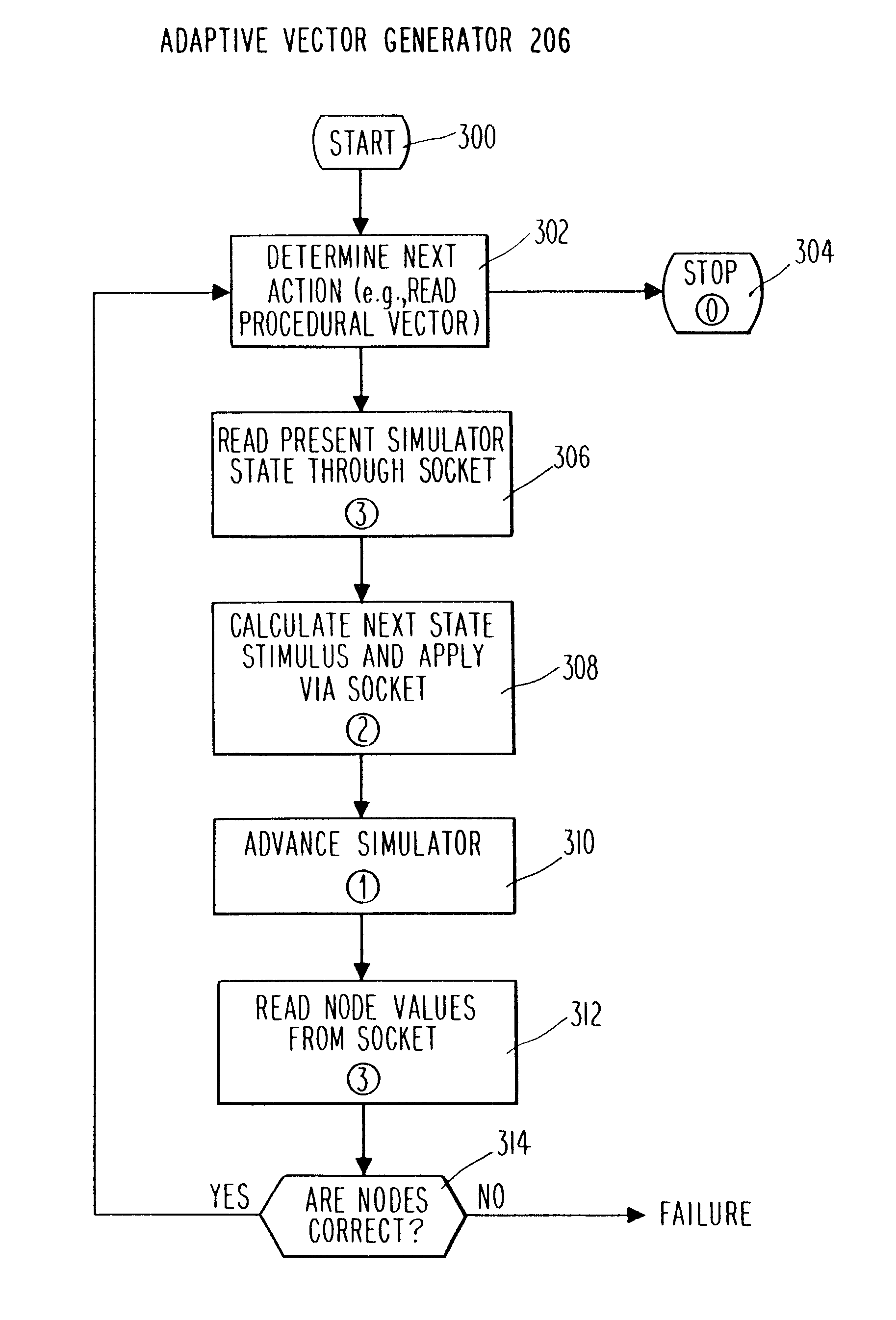
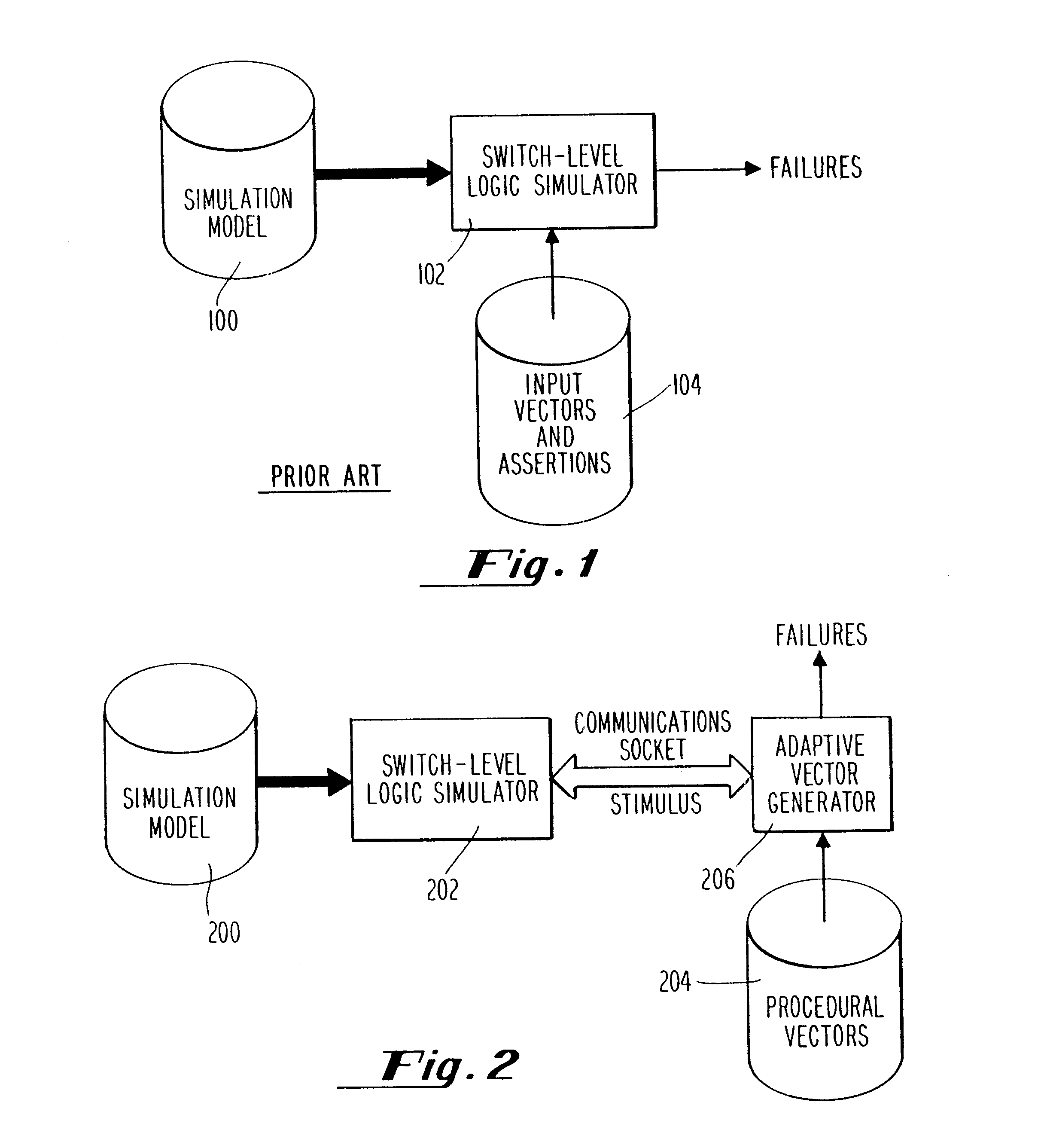
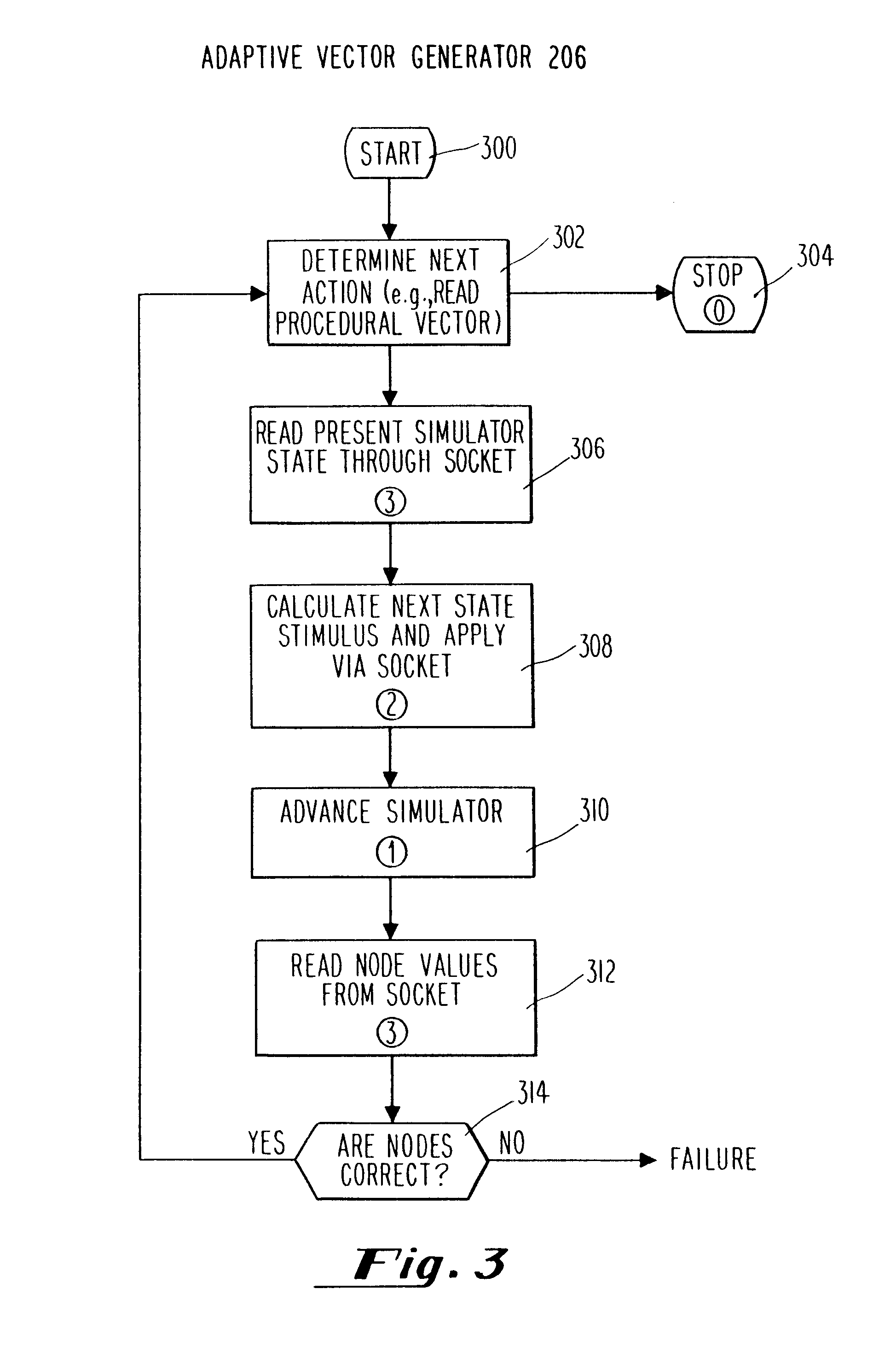
A system and method which affords the above-mentioned and other beneficial features in accordance with a presently preferred exemplary embodiment of the invention will be described below with reference to FIGS. 2-6. Those skilled in the art will readily appreciate that the description given herein with respect to those figures is for explanatory purposes only and is not intended in any way to limit the scope of the invention. All questions regarding the scope of the Invention may be resolved by referring to the appended claims.

The present invention differs from prior art logic simulation systems in that an input stimulus may be applied interactively to the logic simulator from a keyboard, from a data file, or from a UNIX.RTM. socket. As known to those skilled in the art, a ARPA / Berkeley UNIX.RTM. socket is a communication pathway which is established from one UNIX.RTM. process to another UNIX.RTM. process. The two UNIX.RTM. processes can either be on the same machine or be on differ...


PUM


Abstract

A communications socket between a logic simulator and a system for generating input stimuli based on the current state of the logic simulator is provided. Input stimuli to the logic simulator for use in implementing a particular circuit design simulation are calculated by interfacing an input program which models the function of the circuit being designed with the logic simulator. The lines in this input program are converted by an adaptive vector generator into communications signals which are understandable by the logic simulator so that the desired simulation may take place. The input program thus enables the adaptive vector generator to behaviorally model complex logical systems that the logic simulator model is only a part of and allows for more accurate and detailed simulation. The adaptive vector generator does this by determining the next input vector state in accordance with the present state of the logic simulator model as received from the communications socket. In other words, based on the state data received from the logic simulator, the adaptive vector generation automatically calculates the next stimulus pattern for the logic simulator model and provides this stimuli to the logic simulator through the communications socket. This technique removes the tediousness of the prior art techniques in that the design engineer no longer needs to specify every input step and to anticipate the output state of the circuit.

Description

1. Field of the InventionThe present invention relates to a bidirectional socket stimulus interface for a logic simulator, and more particularly, to a bidirectional socket stimulus interface which allows input stimuli to be provided interactively from a keyboard, from a data file, or from a UNIX.RTM. socket directly to the logic simulator. The system of the invention also allows the user to provide input stimuli which behaviorally model complex logic systems that the logic simulator model is part of by basing the state of the next input vector on the present state of the logic simulator.2. Description of the Prior ArtWhen designing integrated circuits for performing particular functions, design engineers have traditionally drawn schematic diagrams of the proposed circuit setting forth all of the elements and interconnections necessary for the circuit to perform the desired functions. From the schematic diagrams, prototype circuits were built and tested. Before the advent of computer...

Claims


Application Information

Patent Timeline
IPC IPC(8): G06F17/50G06F11/25G06F19/00
CPCG06F17/5022G06F30/33G06F11/26
Inventor HEIKES, CRAIG
Owner AVAGO TECH WIRELESS IP SINGAPORE PTE
Learn More