Wake turbulence detecting system

a turbulence detection and wake technology, applied in the direction of landing aids, instruments, using reradiation, etc., can solve the problems of short life, deterioration of controllability, and inability to afford highly trustworthy aircraft traffic control

Inactive Publication Date: 2002-07-23
MITSUBISHI ELECTRIC CORP
View PDF10 Cites 49 Cited by
  • Summary
  • Abstract
  • Description
  • Claims
  • Application Information

AI Technical Summary

Problems solved by technology

As for the scale of wake turbulence, a diameter of a vortex may extend to a few hundred feet, deteriorating the controllability of the following aircraft entering the trail.
On the other hand, when wind is strong, the wake turbulence may spread, resulting in short lifetime but possible drift downstream from where it started, affecting aircraft flying in other sky areas.
For example, though the wake turbulence detecting system shows nonexistence of wake turbulence, if it is unclear whether wake turbulence really does not exist or exists but merely cannot be detected, highly trustworthy aircraft traffic control can not be afforded.

Method used


Image

  • Wake turbulence detecting system
  • Wake turbulence detecting system
  • Wake turbulence detecting system

Examples


first embodiment

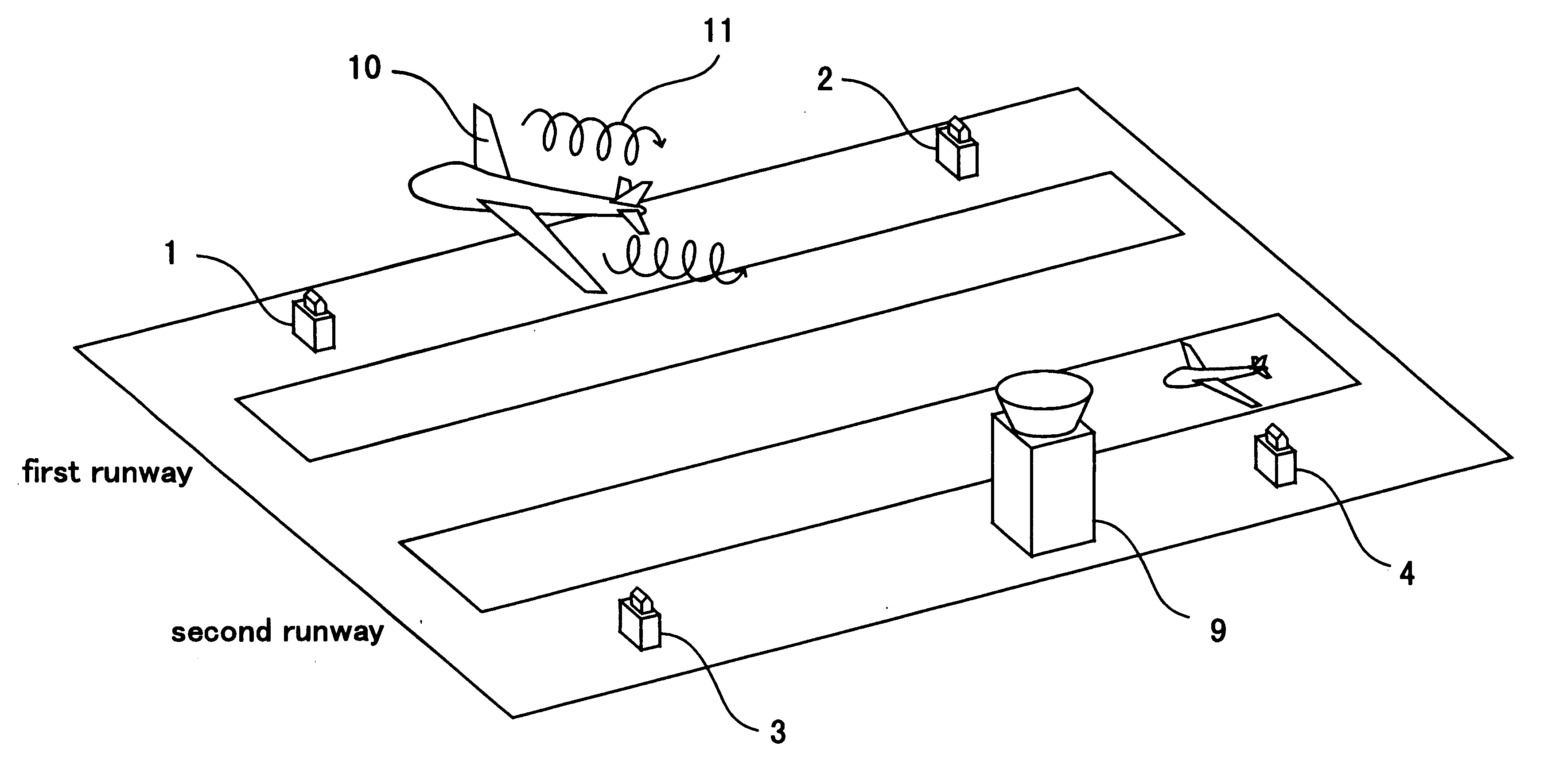
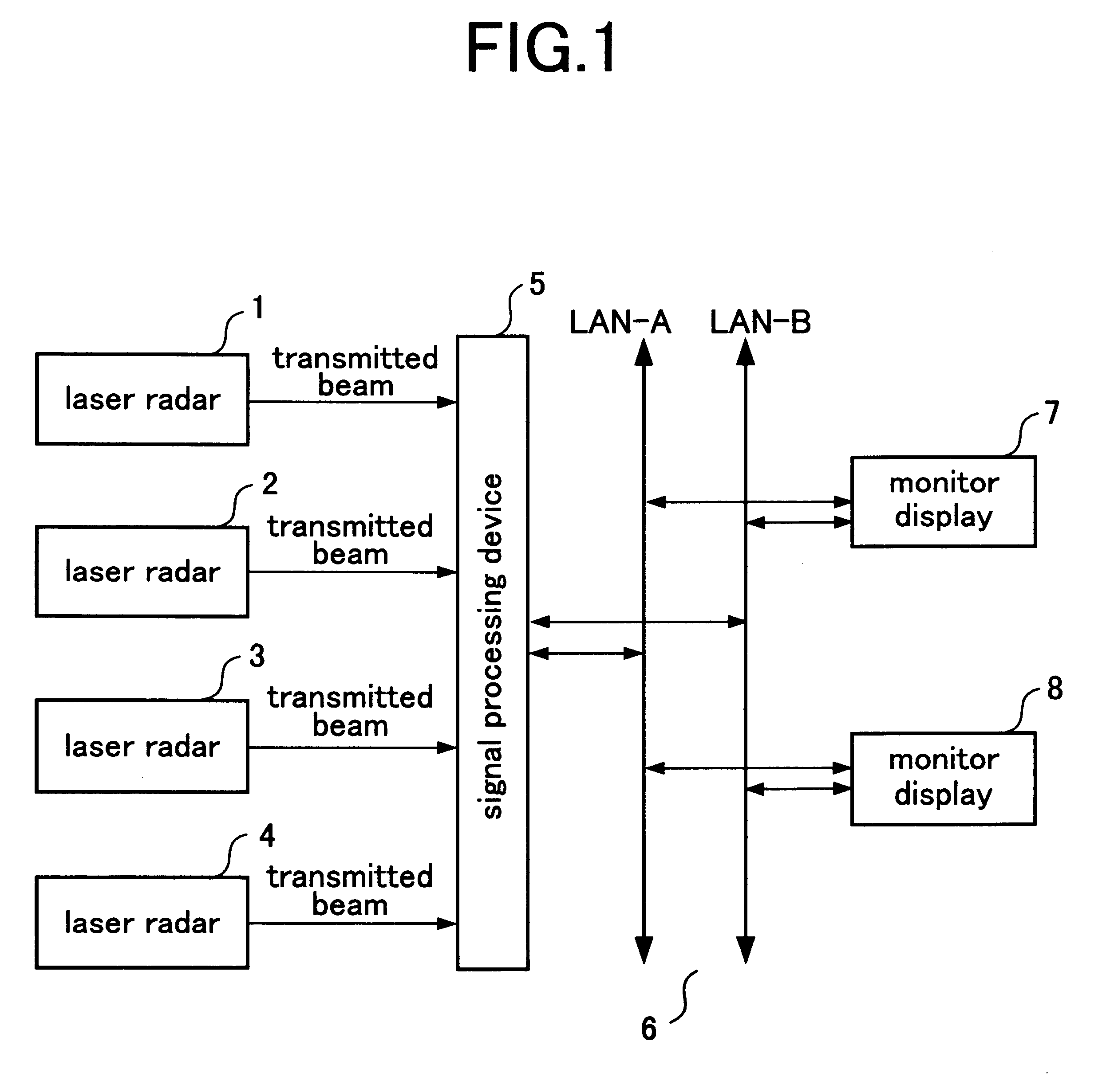
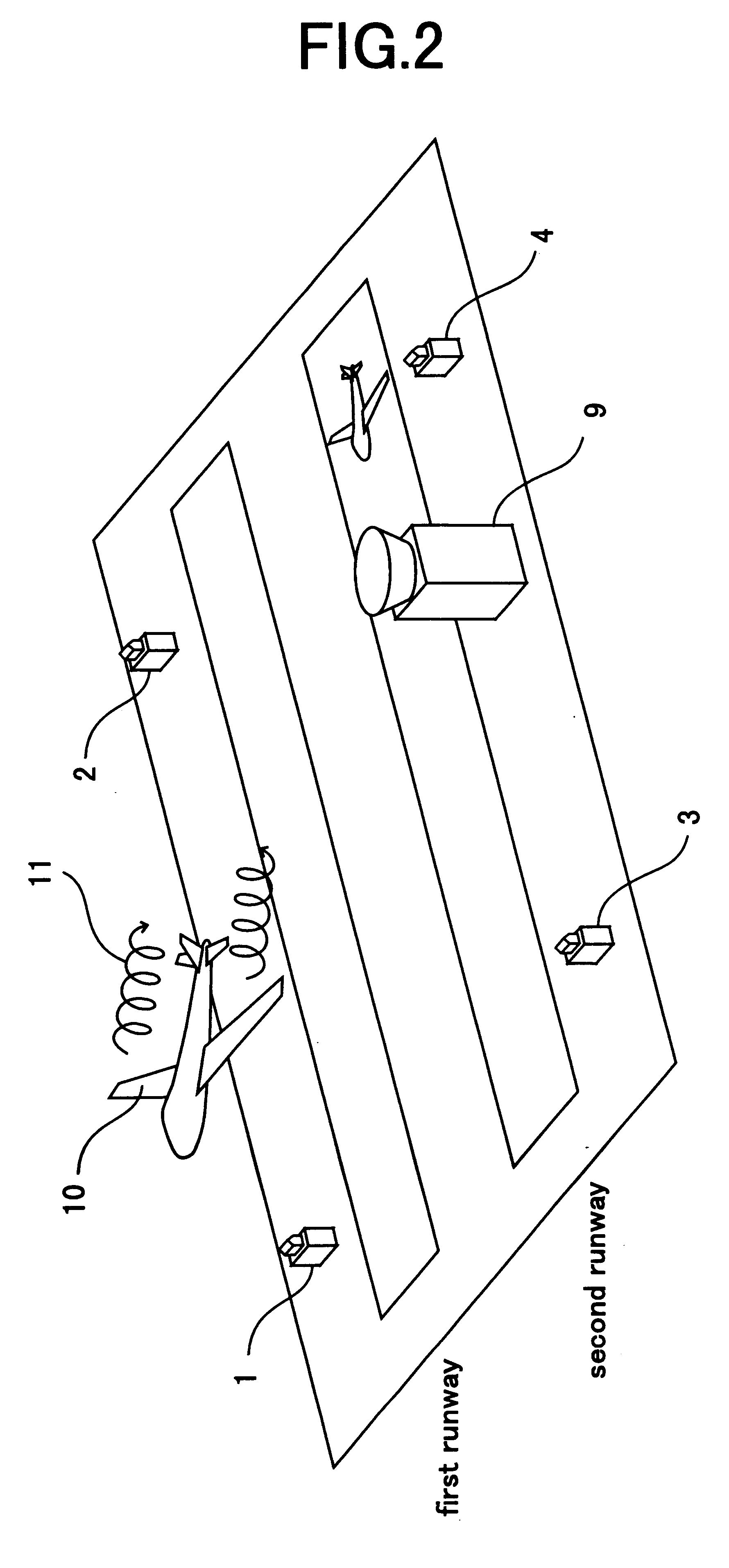
FIG. 1 is a block diagram which shows constitution of a wake turbulence detecting system related to the first embodiment of the present invention. In FIG. 1, reference number 1 denotes a first laser radar which is arranged in the vicinity of the first runway for emitting laser beam and receiving the reflected laser beam reflected back by aerosol in the atmosphere. Reference number 2 denotes a second laser radar arranged at a position differing from that of the first laser radar in the vicinity of the first runway same as the first laser radar. Reference number 3 denotes a third laser radar arranged in the vicinity of the second runway. Reference number 4 denotes a fourth laser radar arranged at a position differing from that of the third laser radar in the vicinities of the second runway same as the third laser radar. Reference number 5 denotes a signal processing device detecting the wake turbulence from the reflected laser beam output by each laser radar 1, 2, 3 and 4 and displayi...

second embodiment

The wake turbulence detecting system related to the first embodiment detects the wake turbulence by means of both first laser radar 1 and second laser radar 2. The wake turbulence detecting system detecting wake turbulence by means of two laser radar, has an advantage that even though the aircraft flies into the blind spot of one laser radar, the other laser radar catches the aircraft making it possible to detect wake turbulence. However, keeping the blind area of each laser radar in memory beforehand, radar that detects wake turbulence may be switched according to the position of an aircraft.

FIG. 8 is a block diagram which shows constitution of a wake turbulence detecting system related to the second embodiment. In FIG. 8, reference number 23 denotes laser radar selecting part which selects either first laser radar 1 or second laser radar 2 for detecting the wake turbulence. Reference number 24 denotes memory means, in which is stored blind spots of first laser radar 1 and second l...


PUM

PropertyMeasurementUnit
diameteraaaaaaaaaa
velocityaaaaaaaaaa
areaaaaaaaaaaa

Abstract

Reducing blind spots of a laser radar observing wake turbulence is required for detecting efficiently the wake turbulence which appears behind the main wings of an aircraft and affects the flight of other aircraft.A first laser radar a and second laser radar each emit a laser beam from different positions. A signal processing device produces wake turbulence information based on the reception signal of the first and second laser radar. Further, the signal processing device specifies wake turbulence information for producing display data either by making a composite of wake turbulence information of two laser radar whose observation areas do not overlap each other or by selecting the larger value of wake turbulence information from two laser radars whose observation areas overlap each other and produces display data for indicating wake turbulence information on monitor display based on the specified wake turbulence information.

Description

1. Field of the InventionThe present invention relates to a wake turbulence detecting system detecting by means of laser radar deployed in an airport wake turbulence which appears behind main wings of an aircraft during takeoff or landing and continues to exist along the trail of the aircraft.2. Description of the Background ArtWake turbulence is a turbulence winding up vortexes rotating in opposite directions to each other, generated backward of right and left main wings of a flying aircraft. As for the scale of wake turbulence, a diameter of a vortex may extend to a few hundred feet, deteriorating the controllability of the following aircraft entering the trail. When wind is weak, wake turbulence continues to exist in consonance with a trail of an aircraft for a few minutes. Lifetime of the wake turbulence gets longer especially early in the morning when wind is slight and strong radiational cooling occurs. On the other hand, when wind is strong, the wake turbulence may spread, re...

Claims


Application Information

Patent Timeline
Patent Type & Authority Patents(United States)
IPC IPC(8): G01P5/26G01P5/00G01S17/00G01S17/95G01S17/87B64F1/18G01S17/06G01S17/88
CPCG01P5/26G01S17/87G01S17/95Y02A90/10
Inventor OOGA, YASUISA
Owner MITSUBISHI ELECTRIC CORP
Why Eureka
Try Eureka