
Pour tube with improved flow characteristics

a technology of flow characteristics and pipe tubes, applied in the field of pipe tubes, can solve problems such as clogging of pipe holes, affecting the steady discharge of liquid, and complicating processing

Inactive Publication Date: 2002-07-30
VESUVIUS USA CORP
View PDF20 Cites 46 Cited by
  • Summary
  • Abstract
  • Description
  • Claims
  • Application Information

AI Technical Summary

Problems solved by technology

Factors, which can disrupt the steady discharge, include asymmetric flow of molten metal and clogging of the bore.
The disparate velocities can cause pulsing and excessive turbulence upon exiting the bore, thereby complicating processing and decreasing the quality of the finished product.
Throttling devices, such as stopper rods or slide gate valves, can partially obstruct the entrance to the bore, and cause the steam of molten metal to enter the bore off the centerline.
Precipitates may also clog or restrict the bore so as to disrupt steady discharge of the molten metal.
Alumina deposits can lead to restrictions and clogging that can stop or substantially impede the smooth and steady flow of molten steel.
Tubes may be unclogged using an oxygen lance; however, lancing disrupts the casting process, reduces refractory life, and decreases casting efficiency and the quality of the steel produced.
A total blockage of the bore by precipitates decreases the expected life of the pour tube and is very costly and time-consuming to steel producers.
Unfortunately, gas injection requires large volumes of gas, complicated refractory designs, and is not always an effective solution.
Gas may also dissolve or become entrapped within the metal causing problems in metal quality including pinhole defects in the steel.
These compositions tend to crack at high temperature, and, during casting, they may hydrate and dissipate.
For these reasons, their useful life is limited.
Such refractories can be expensive, impractical, and manufacturing can be both hazardous and time consuming.
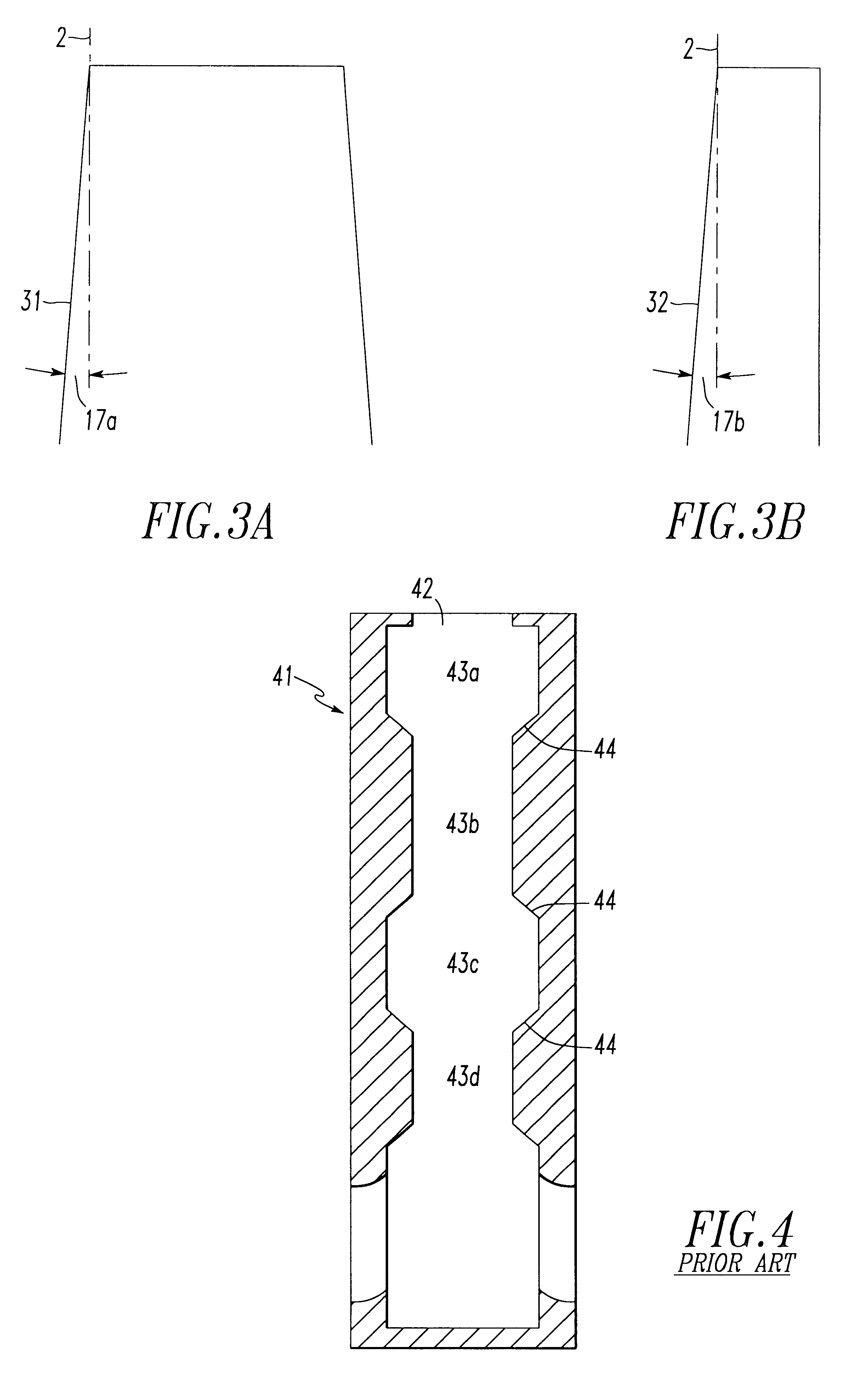
Non-turbulent flow permits alumina to buildup on the surface of the bore, and can lead to clogging of the bore away from the step.
Further, no prior art design simultaneously describes a pour tube that reduces asymmetric flow of molten metal passing through the pour tube's bore and the relationship between reduced asymmetric flow and alumina clogging.

Method used


Image

  • Pour tube with improved flow characteristics
  • Pour tube with improved flow characteristics
  • Pour tube with improved flow characteristics

Examples


Embodiment Construction

The invention comprises a pour tube having a throughflow bore for use in the continuous casting of molten metal. A pour tube includes shrouds, nozzles, and other refractory pieces for containing a stream of molten metal, including, for example, submerged entry shrouds and nozzles, inner nozzles, and well-block nozzles. The stream passes from an upstream position, through the bore, to a downstream position. The bore comprises a plurality of fluidly connected sections. The sections are most frequently linked in series so that the stream passes from an upstream section to a first downstream section, and optionally to a second and subsequent downstream section(s).

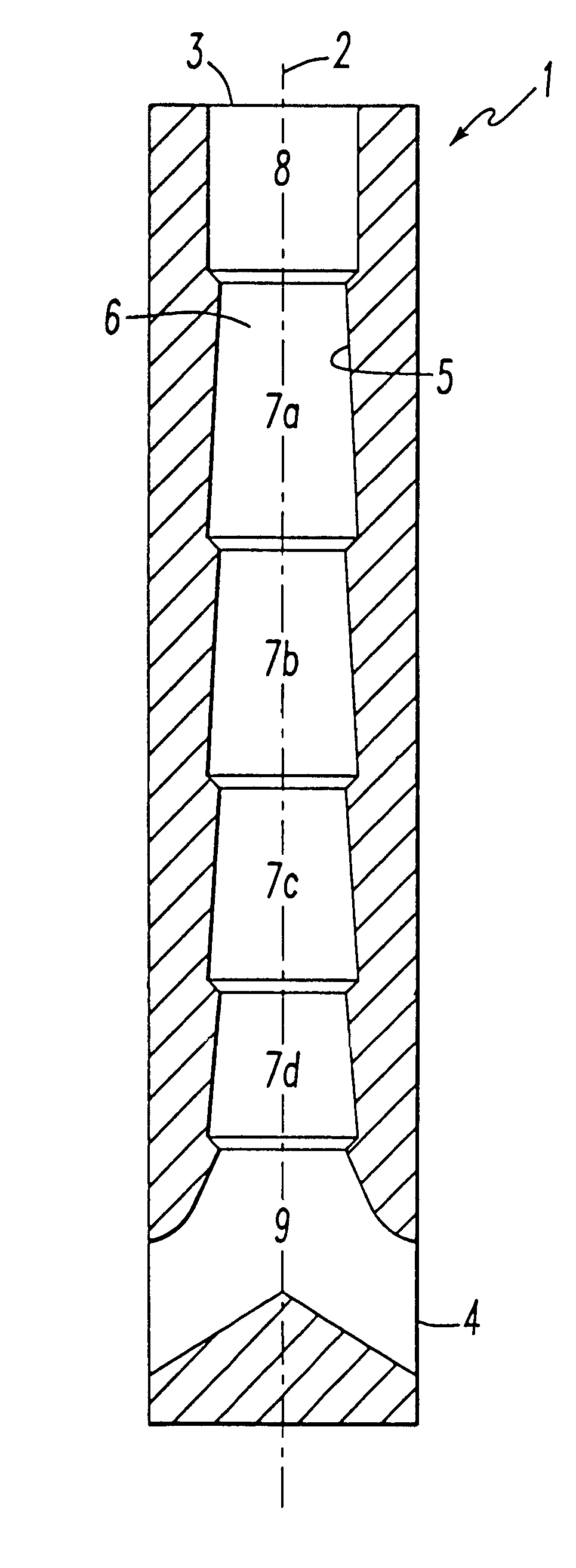
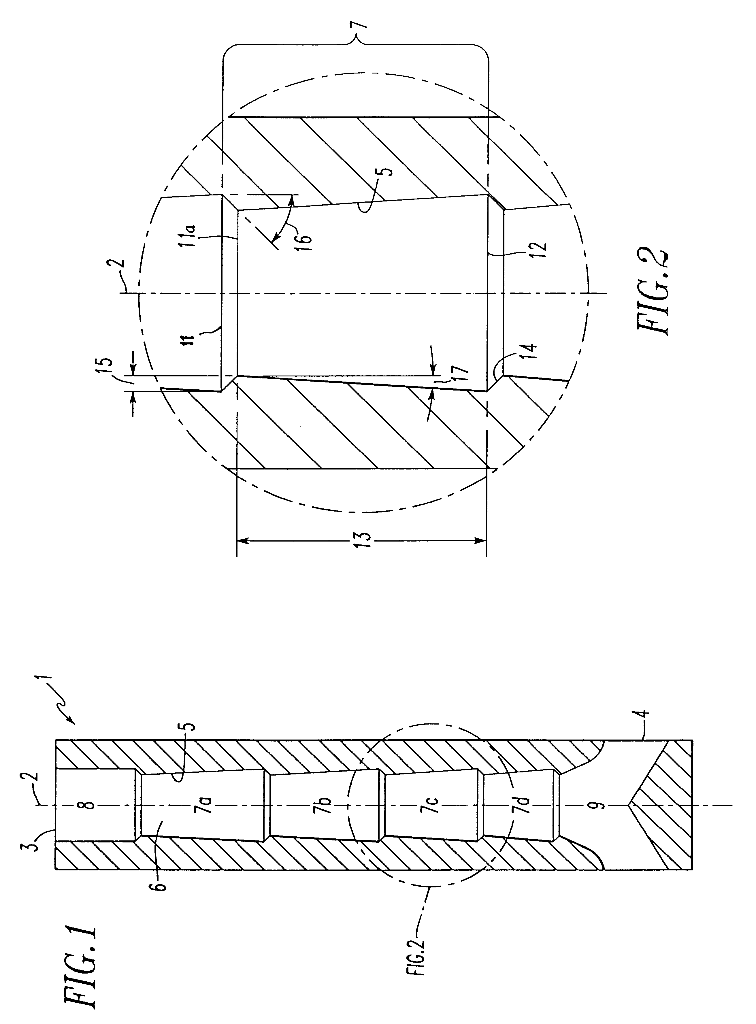
As shown in FIG. 1, the pour tube (1) has a longitudinal axis (2) extending from an upstream position (3) to a downstream position (4). The inside surface (5) of the pour tube (1) defines a throughflow bore (6) along the longitudinal center axis (2). The bore (6) is divided into a plurality of sections (7a-d) fluidly connected ...


PUM

PropertyMeasurementUnit
Fractionaaaaaaaaaa
Angleaaaaaaaaaa
Angleaaaaaaaaaa

Abstract

A pour tube for use in the continuous casting of a stream of molten metal has a bore comprising a plurality of fluidly connected sections that improve the flow of molten metal through the bore. The sections reduce asymmetric flow of the molten metal stream and the likelihood of precipitates clogging the bore. Each section comprises a converging portion and a diverging portion. The converging portion deflects the stream toward the center of the bore, while the diverging portion diffuses the stream. The sections may comprise a plurality of frusto-conical sections. The cross-sectional areas of the sections may increase, decrease, or remain the same size from an upstream to a downstream position.

Description

1. Field of the InventionThe invention relates to a pour tube for use in the continuous casting of molten metal. More particularly, the invention describes an article and method for improving flow characteristics of the molten metal.2. Description of the Prior ArtIn the continuous casting of metal, particularly steel, a stream of molten metal is typically transferred via a refractory pour tube from a first metallurgical vessel into a second metallurgical vessel or mold. Such tubes are commonly referred to as shrouds or nozzles, and possess a bore through which the metal passes. One important function of a pour tube is to discharge the molten metal in a smooth and steady manner without interruption or disruption. A smooth, steady discharge facilitates processing and can improve the finished product.Factors, which can disrupt the steady discharge, include asymmetric flow of molten metal and clogging of the bore. Asymmetric flow may develop before or after the stream is in the bore. Fo...

Claims


Application Information

Patent Timeline
IPC IPC(8): B22D41/50
CPCB22D41/50
Inventor HEASLIP, LAWRENCE JOHNDORRICOTT, JAMES DEREKROBINSON, QUENTIN
Owner VESUVIUS USA CORP
Learn More