Cold junction compensation for multiple thermocouples

a multi-thermal and cold junction technology, applied in the direction of instruments, thermometers using mean/integrated values, heat measurement, etc., can solve the problems of unsuitable cables, unacceptably expensive thermocouple installation, and relatively high materials costs

Inactive Publication Date: 2002-07-30
WESTON AEROSPACE
View PDF18 Cites 23 Cited by
  • Summary
  • Abstract
  • Description
  • Claims
  • Application Information

AI Technical Summary

Problems solved by technology

A disadvantage of using R-type thermocouples is that the materials are relatively expensive.
(beyond which such cables are unsuitable).
In such situations the thermocouple installation becomes unacceptab

Method used


Image

  • Cold junction compensation for multiple thermocouples
  • Cold junction compensation for multiple thermocouples
  • Cold junction compensation for multiple thermocouples

Examples


Embodiment Construction

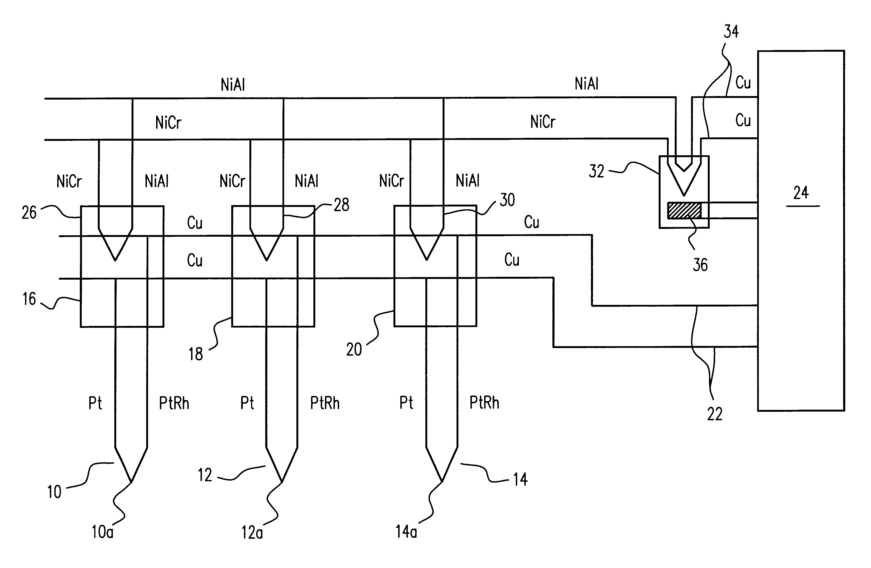
Referring to FIG. 1, this shows in schematic form a plurality of thermocouples 10, 12, 14 of Platinum / Platinum-Rhodium material. In use these thermocouples are housed in probes, either individually or else in pairs and are mounted for example in aero engines, such that the respective tips 10a, 12a, 14a will constitute hot junctions (or hot thermojunctions) located inside the gas stream in the engine to measure the average total gas temperatures in the engine which might typically be of the order of 1200.degree. C. to 1600.degree. C. At the other ends (the cold junctions--cold thermojunctions) the thermocouple wires are terminated in terminal heads 16, 18 and 20 mounted on the exterior of the engine at a much lower temperature which might typically be of the order of 300.degree. C. to 400.degree. C. The thermocouples 10,12, 14 are connected in parallel to copper wires 22 which extend to conventional analytical circuitry, represented by 24. The voltage across the copper wires 22 is ge...


PUM


Abstract

A system for measuring average temperature including a plurality of measurement thermocouples (10,12,14) connected in parallel to measurement apparatus (24) by two signal wires (22) of a material different to that of the measurement thermocouples (10,12,14). Compensation thermocouples (26,28,30) are located at the cold junctions (16,18,20) of the measurement thermocouples (10,12,14) and connected to the measurement apparatus (24).

Description

1. Field of the InventionThe present invention relates to a system for cold junction compensation for a plurality of thermocouples.2. Discussion of Prior ArtIn some applications, such as temperature measurement in aero engines, the temperatures to be measured are in excess of those which can be tolerated by conventional NiCr / NiAl thermocouples (commonly referred to as K-type thermocouples). The total gas temperature (TGT) inside some new jet engines is above 1200.degree. C. which is above the reliable operating limit for a K-type thermocouple. Because of this it is desirable to fabricate thermocouples for such high temperature applications from Platinum and Platinum-Rhodium (Pt / PtRh--commonly referred to as R-type thermocouples although other reference symbols are sometimes used). Such thermocouples have a much higher tolerance to high temperatures.A thermocouple may be used in the measurement of temperature by measurement of a thermal voltage generated therein which is a function o...

Claims


Application Information

Patent Timeline
IPC IPC(8): G01K7/13G01K3/00G01K7/02G01K3/06
CPCG01K3/06G01K7/13
Inventor KULCZYK, WOJCIECH K.
Owner WESTON AEROSPACE
Why Eureka
Try Eureka