Valve for controlling fluids

Inactive Publication Date: 2002-08-06
ROBERT BOSCH GMBH
View PDF9 Cites 33 Cited by
  • Summary
  • Abstract
  • Description
  • Claims
  • Application Information

AI Technical Summary

Problems solved by technology

However, it has been found that overswings of the closing body occur when the closing body is to be brought to a middle position between the two valve seats.
As soon as the closing body swings too far in the direction of the first or the second valve seat, this can adversely cause imprecisions in metering the injection quantity.
It is possible for the middle position of the closing body betw

Method used


Image

  • Valve for controlling fluids
  • Valve for controlling fluids
  • Valve for controlling fluids

Examples


Embodiment Construction

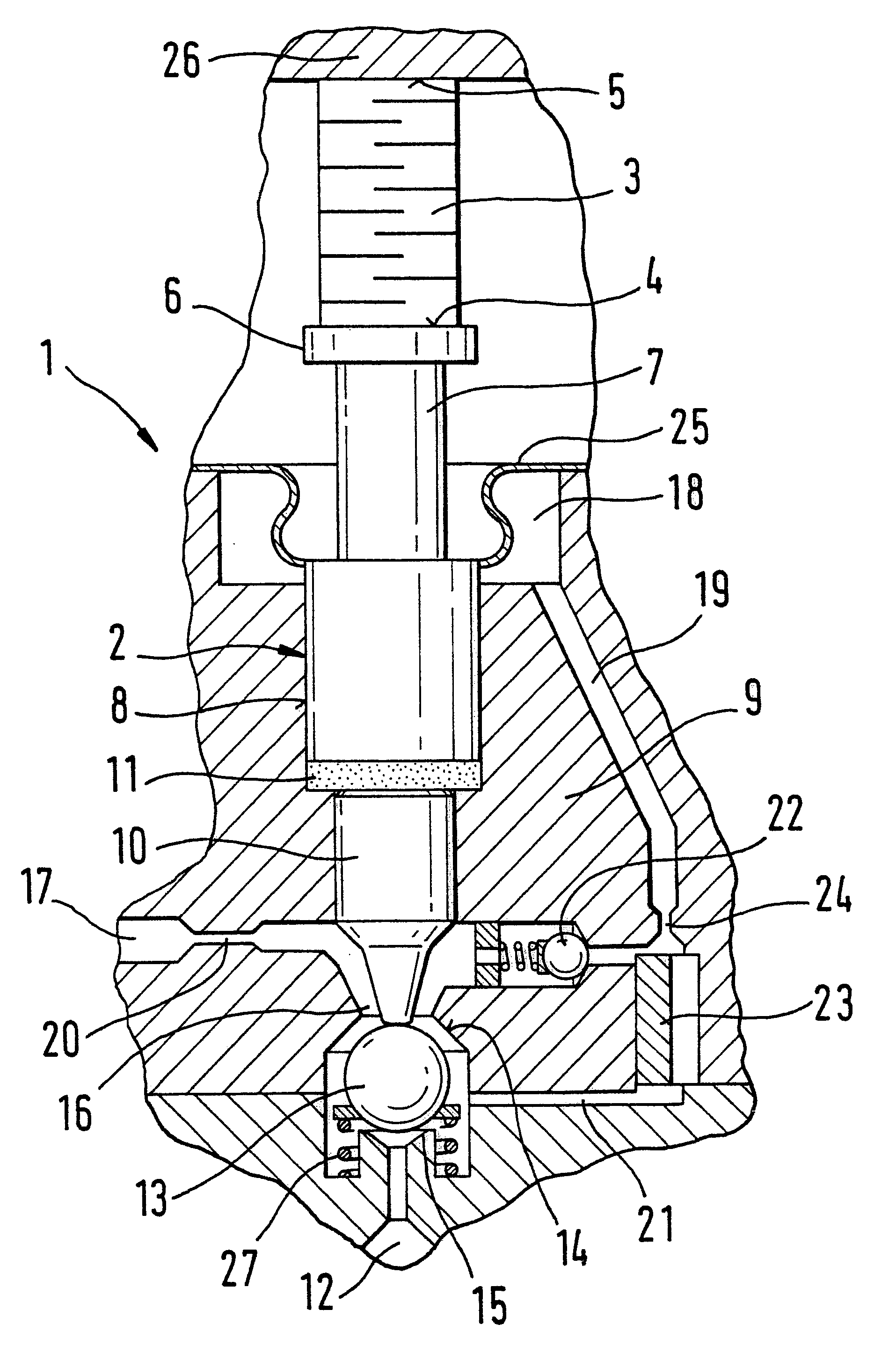
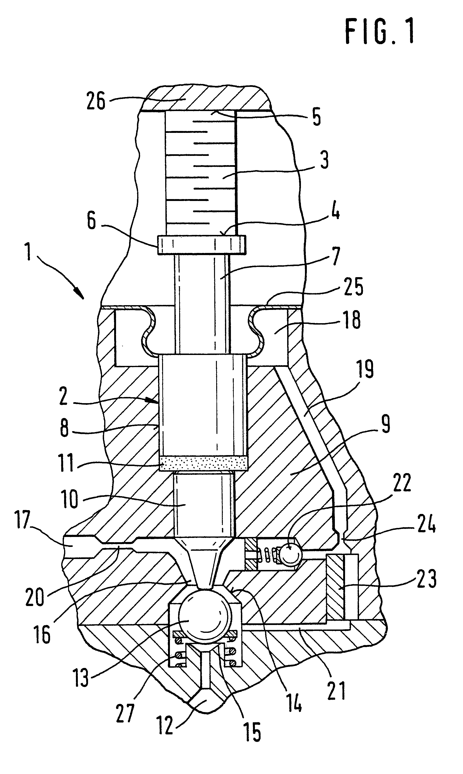
The first exemplary embodiment shown in FIG. 1 illustrates a use of the valve of the invention in a fuel injection valve 1 for internal combustion engines of motor vehicles. The fuel injection valve 1 is embodied here as a common rail injector, and the fuel injection is controlled via the pressure level in a valve control chamber 12, which is connected to a high-pressure supply.

For setting an injection onset, injection duration, and injection quantity via force ratios in the fuel injection valve 1, a multiple-piece valve member 2 is triggered via a piezoelectric unit, embodied as a piezoelectric actuator 3 and disposed on the side of the valve member 2 toward the valve control chamber and the combustion chamber.

The piezoelectric actuator 3 is made up of multiple layers, and on its side toward the valve member 2 it has an actuator head 4 and on its side remote from the valve member it has an actuator foot 5, which is braced on a wall 26. Via a bearing 6, a control piston 7 of the val...


PUM


Abstract

A valve (1) for controlling liquids is embodied with a piezoelectric unit (3) for actuating a valve member (2) that is axially displaceable in a bore (8) of a valve body (9). One end of the bore (8) adjoins a valve system pressure chamber (18) defined by a sealing element (25), and its other end adjoins a valve low-pressure chamber (16), which has a leak drainage conduit (17) and which communicates with the valve system pressure chamber (18) via a compensation conduit (19), which has a pressure limiting device (20, 23') and a filling device (23, 23'). The valve member (2) is assigned a valve closing member (13), which cooperates in such a way with at least two valve seats (14, 15), disposed in the valve low-pressure chamber (16), for opening and closing the valve (1) that in a closing position it separates the valve low-pressure chamber (16) from a valve control chamber (12), which is at high pressure, and in an intermediate position between the valve seats (14, 15) it fluidically connects the valve low-pressure chamber (16) to the valve control chamber (12); at least one damping device (20, 23', 24) for damping the control motions of the valve member (2) is provided and briefly generates hydraulic counterforces (Fig.).

Description

PRIOR ARTThe invention is based on a valve for controlling liquids as defined in more detail by the preamble to claim 1.From German Patent Disclosure DE 197 328 02, a fuel injection device for internal combustion chambers is known that has a high-pressure fuel source. The fuel injection device has two valve seats, which cooperate with sealing faces of a closing body in a motion sequence upon actuation by a piezoelectric drive; initially, in the closing position, the closing body is located on the first valve seat and is then moved into an intermediate position between the valve seats, and then regains a closing position, but on the second valve seat.In this way, because of the course of motion of the closing body from one valve seat to the other, a brief relief of a valve control chamber is attained, by way of whose pressure level an opening and closing position of a valve needle in the fuel injection device, which is embodied as force-balanced, is determined, and the fuel injection...

Claims


Application Information

Patent Timeline
IPC IPC(8): F02M59/46F02M61/16F02M61/00F02M59/00F02M45/04F02M45/00F02M47/02F02M63/00F02M47/00F02M51/00F02M61/20F16K31/02F16K51/02H02N2/02
CPCF02M45/04F02M47/027F02M61/167F02M63/0026F02M2200/304F02M2200/705
Inventor STOECKLEIN, WOLFGANG
Owner ROBERT BOSCH GMBH
Why Eureka
Try Eureka