
Optical projector with image enlarging and projecting capability and heat insulating and cooling means

Inactive Publication Date: 2002-08-06
SEIKO EPSON CORP
View PDF4 Cites 38 Cited by
  • Summary
  • Abstract
  • Description
  • Claims
  • Application Information

AI Technical Summary

Benefits of technology

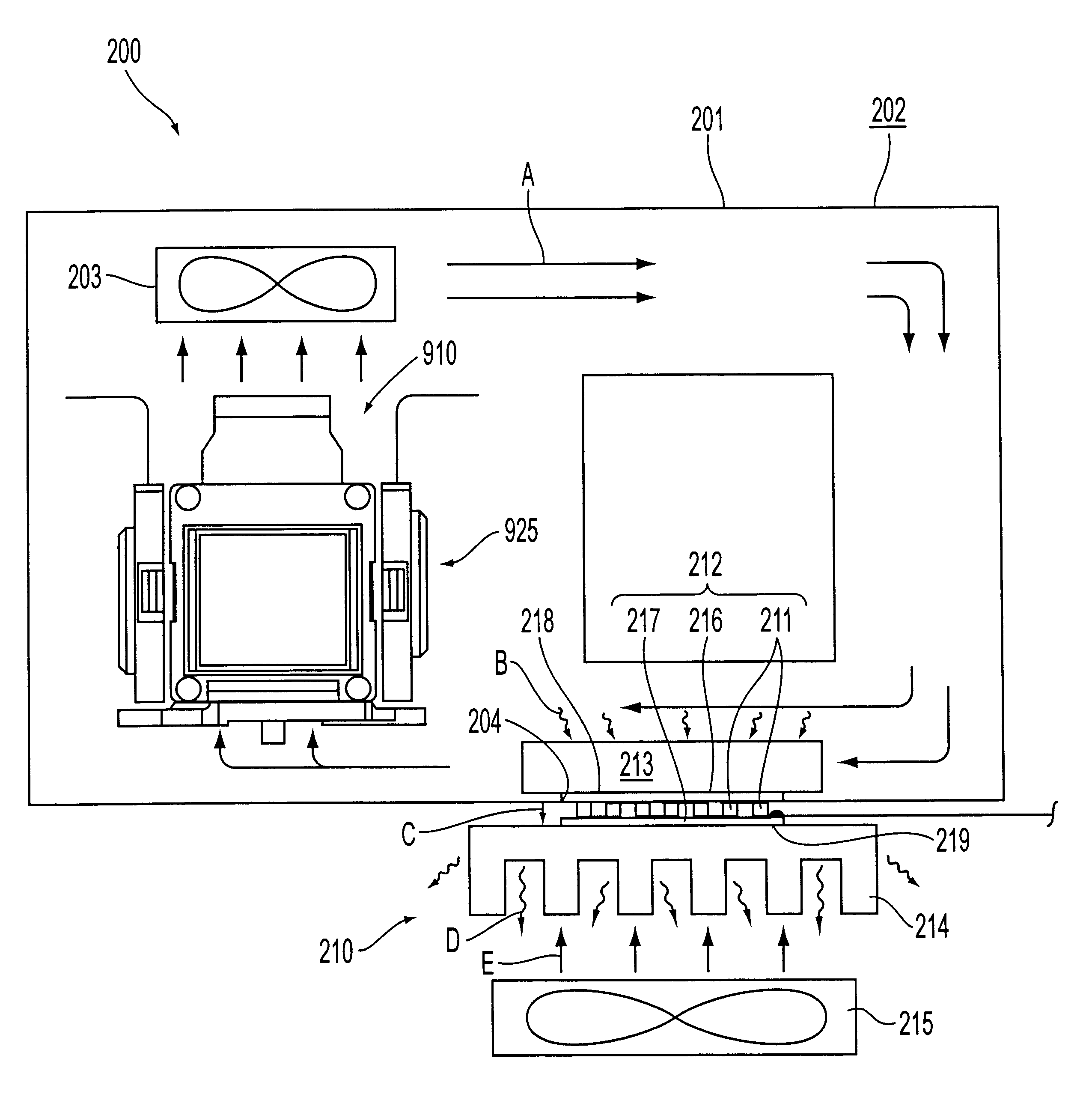
In the present invention as described above, the optical path from the electrooptical device to the projection lens is enclosed by the enclosing structure, and the air inside the enclosing structure is cooled by the cooling element, whereby the electrooptical device can be efficiently cooled. In addition, since the entry of dust or oil mist from the outside is prevented by the enclosing structure, the dust or oil mist does not adhere to the electrooptical device and the like, and the image quality of the projector can be stably secured over a long period of time.
This allows the circulating fan to forcibly circulate the air inside the enclosing structure, whereby the electrooptical device can be cooled more efficiently.
With this configuration, by exposing the heat absorption surface of the thermoelectric transducer to the inside of the enclosing structure and exposing the heat radiation surface to the outside of the enclosing structure, heat included in the air inside the enclosing structure can be easily radiated to the outside of the enclosing structure, whereby the structure of the cooling element can be simplified and reduced in size.
If the heat absorption surface is provided with the transfer member in this way, by disposing the heat transfer member in an airflow inside the enclosing structure, heat exchange between the internal air and the heat transfer member is smoothly affected, and the heat inside the enclosing structure can be efficiently transferred to the heat absorption surface.
If the heat radiation surface is provided with the heat transfer member, heat can be efficiently radiated from the heat transfer member when the heat is radiated to the outside of the enclosing structure from the heat radiation surface. That is, by providing the heat transfer members on the heat absorption surface and the heat radiation surface, heat absorption operation and heat radiation operation of the thermoelectric transducer can be efficiently affected.
This allows a heat transfer member to be forcibly cooled. Therefore, the temperature rise inside the device due to the heat radiation from the heat transfer member can be prevented. In addition, since the heat transfer member is forcibly cooled, heat is efficiently transferred from the heat radiation surface to the heat transfer member, and heat radiation operation of the thermoelectric transducer is efficiently affected also in this respect.

Problems solved by technology

Since the optical modulation devices are important portions for forming an optical image according to image information, if dust or oil mist adheres to the surface of the liquid crystal panel or the like, the image quality of the projector will deteriorate.
However, since the optical modulation device, such as the liquid crystal panel, is easily affected by heat, if the optical path from the electrooptical device to the projection lens is enclosed by the enclosing structure as described above, it is difficult to efficiently cool the optical modulation device, i.e., the electrooptical device by introducing cooling air from the outside of the device.
In particular, in a recent trend toward an increase in brightness and a reduction in size of the projector, efficiently cooling the electrooptical device is an important problem.

Method used


Image

  • Optical projector with image enlarging and projecting capability and heat insulating and cooling means
  • Optical projector with image enlarging and projecting capability and heat insulating and cooling means
  • Optical projector with image enlarging and projecting capability and heat insulating and cooling means

Examples


Embodiment Construction

An embodiment of the present invention will now be described with reference to the drawings.

(1) Overall Configuration of the Device

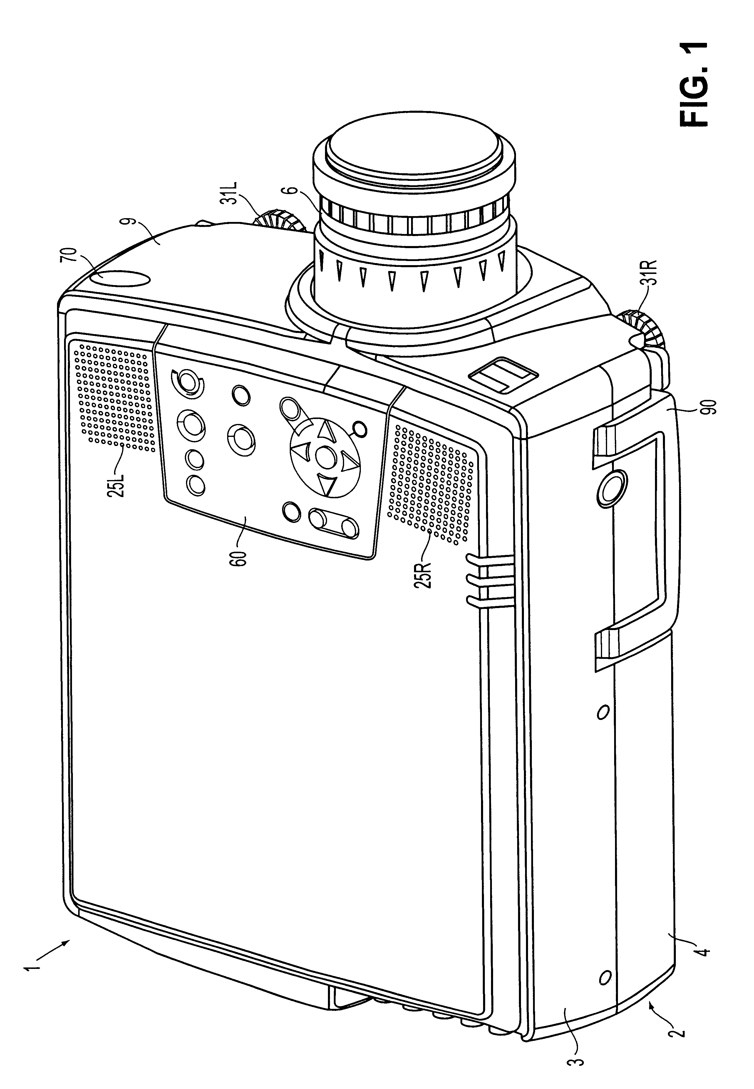
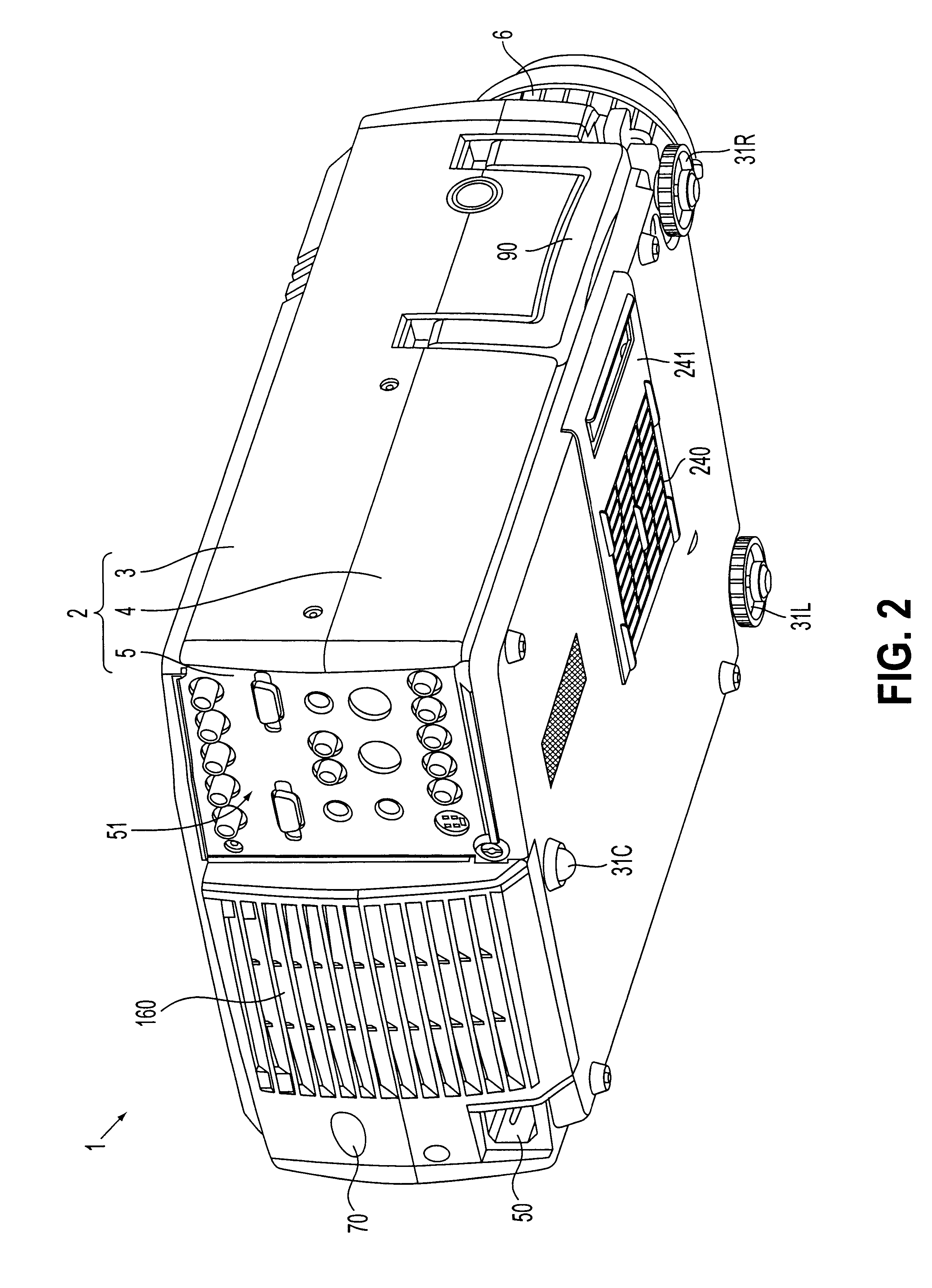
FIGS. 1 and 2 are schematic perspective views of a projector 1 according to this embodiment. FIG. 1 is a perspective view as viewed from the top side, and FIG. 2 is a perspective view as viewed from the bottom side.

The projector 1 is of a type that separates a light emitted from a light source lamp serving as a light source into three primary colors of red (R), green (G), and blue (B), that modulates these color lights according to image information through liquid crystal panels constituting an electrooptical device, that synthesizes the modulated lights of respective colors by a prism (color-synthesizing optical system), and that enlarges and displays the synthesized lights onto a projection plane via a projection lens 6. Components are accommodated in an outer casing 2 serving as housing except a part of the projection lens 6.

(2) Structure of Outer Cas...


PUM


Abstract

A projector includes an enclosing structure that encloses an optical path from an electrooptical device to a projection lens with a heat insulating member, and a thermoelectric transducer for cooling air inside the enclosing structure. Since the enclosing structure is formed by the heat insulating member, the electrooptical device can be efficiently cooled while thermally blocking between the inside and the outside thereof. Since being enclosed, the entry of dust or oil mist from the outside is prevented, and dust or oil mist does not adhere to the electrooptical device and the like.

Description

1. Field of the InventionThe present invention relates to a projector including an electrooptical device for forming an optical image according to image information, and a projection lens for enlarging and projecting the image formed by the electrooptical device.2. Description of Related ArtHitherto, projectors have been used which include a light source, an optical system for modulating light emitted from the light source according to image information to form an optical image, and a projection lens for enlarging and projecting the modulated light. The optical system includes an illuminating optical system for producing a uniform inplane illumination distribution of light emitted from the light source, a color separation optical system for separating the light from the illuminating optical system into three primary colors of red, blue, and green, an electrooptical device for modulating color lights according to image information, and a color-synthesizing optical system for synthesi...

Claims


Application Information

Patent Timeline
IPC IPC(8): C09K5/00G03B21/14G02F1/13G02F1/1333G03B21/16H04N5/74G09F9/00
CPCC09K5/00G03B21/14G03B21/16
Inventor HABA, SHINJI
Owner SEIKO EPSON CORP
Learn More