Rotary shaft sealing system

a sealing system and rotary shaft technology, applied in the field of manufacture and method, can solve the problems of loss or distortion of the dimensional stability of the seal, the effect of elevated fluid pressure and/or pressure surge on the seal is not contemplated nor known, and the leakage of lubricant at the contact lip of the seal, so as to shorten the break-in period of a new seal, prevent displacement and/or distortion of the seal lip, and minimize fluid leakage

Inactive Publication Date: 2002-08-13
ULRICH DONALD
View PDF9 Cites 17 Cited by
  • Summary
  • Abstract
  • Description
  • Claims
  • Application Information

AI Technical Summary

Benefits of technology

In another of the preferred embodiments of this invention, the retention gland geometry, relative to the radial seal, causes fluid to be directed onto the seal, and thus positive hydraulic pressure, so at to instantaneously urge the lip of the seal against the shaft, thereby minimizing fluid leakage past the seal.
In another of the preferred embodiments of this invention (FIG. 3), the rotary lip seal comprises a composite, wherein a back-up element is associated with the seal to physically support the seal and prevent displacement and / or distortion of the seal lip relative to the rotary shaft at start-up; and, to further insure proper and complete seal alignment relative to the rotary shaft.
In another of the preferred embodiments of this invention (FIG. 3), the rotary lip seal incorporates a rotary dam comprising an internal lubricant, which upon erosion during pressure contact with the rotary shaft, imparts a lubricous film at the seal / shaft interface so as to shorten the break-in period of a new seal and, thus, facilitate initial leakage control at the interface of the seal and the rotary shaft.

Problems solved by technology

A common problem with such seals is improper bonding between the plastic and the metal which, when subjected to chemical attack and elevated temperature, causes loss or distortion in dimensional stability of the seal under load, resulting in leaking.
Baisells does not specifically address the use of his seal in a high pressure sealing environment, and, thus, the effects of elevated fluid pressure and / or pressure surges upon his seal are neither contemplated nor known.
It would appear that the fluid dynamics of grease in the roller bearing of the Otto seal is not particularly demanding, nor does it appear that the seal is exposed to pressure surges of lubricant or lubricant pressures which could potentially result in the leakage of lubricant at the contact lip of the seal.
Ott does not specifically address the use of his seal in a high pressure sealing environment, and, thus, the effects of elevated fluid pressure and / or pressure surges upon his seal are neither contemplated nor known.
Rieder does not specifically address the use of his sealing arrangement in a high pressure sealing environment, and, thus, the effects of elevated fluid pressure and / or pressure surges upon his sealing arrangement are neither contemplated nor known.
Also, for unsprung lip seals, the lip relies on the lip stretch around the shaft to give initial sealing and as fluid pressure increases the initial elastomer load is insignificant.
If fluid pressure on the lip causes high frictional heat as the shaft rotates, the rubber heat ages and sets to shaft size.
While such objective is both desirable and apparent, the achievement thereof is beset with numerous probes, including the potential for wear associated with the relative movement (both axial and rotational) of each of these components, a breakdown in the self-lubricating properties of the sealing materials, controlled access of lubricant to the shaft seal interface; and the, maintenance of critical tolerances of these components within this demanding environment.

Method used


Image

  • Rotary shaft sealing system
  • Rotary shaft sealing system
  • Rotary shaft sealing system

Examples


Embodiment Construction

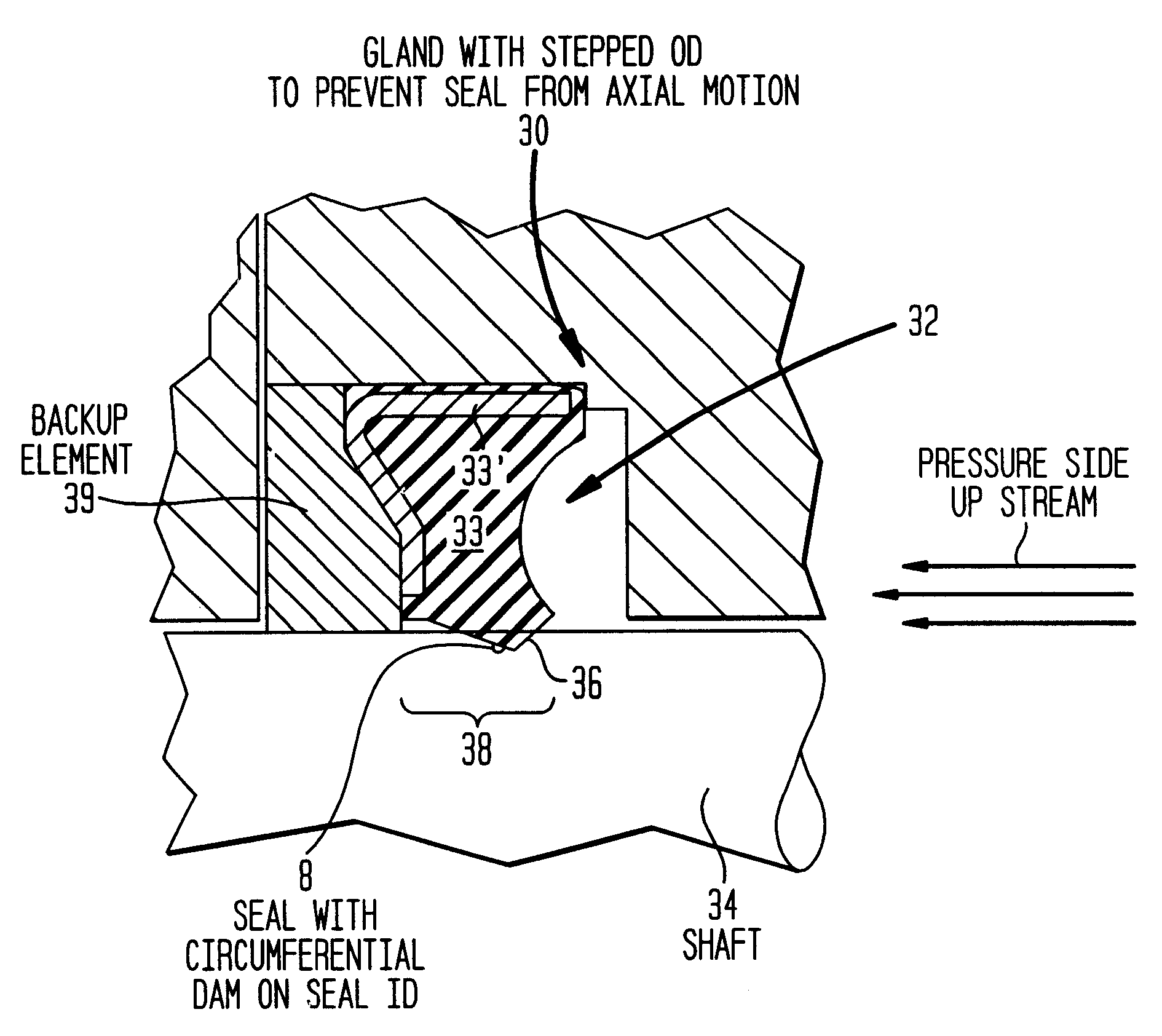
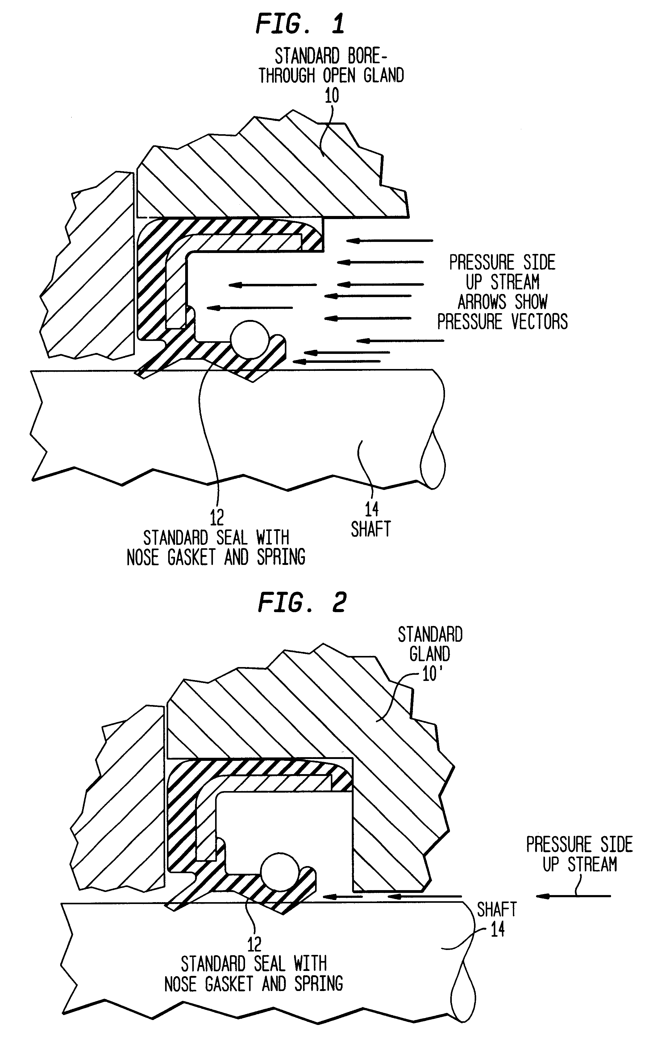
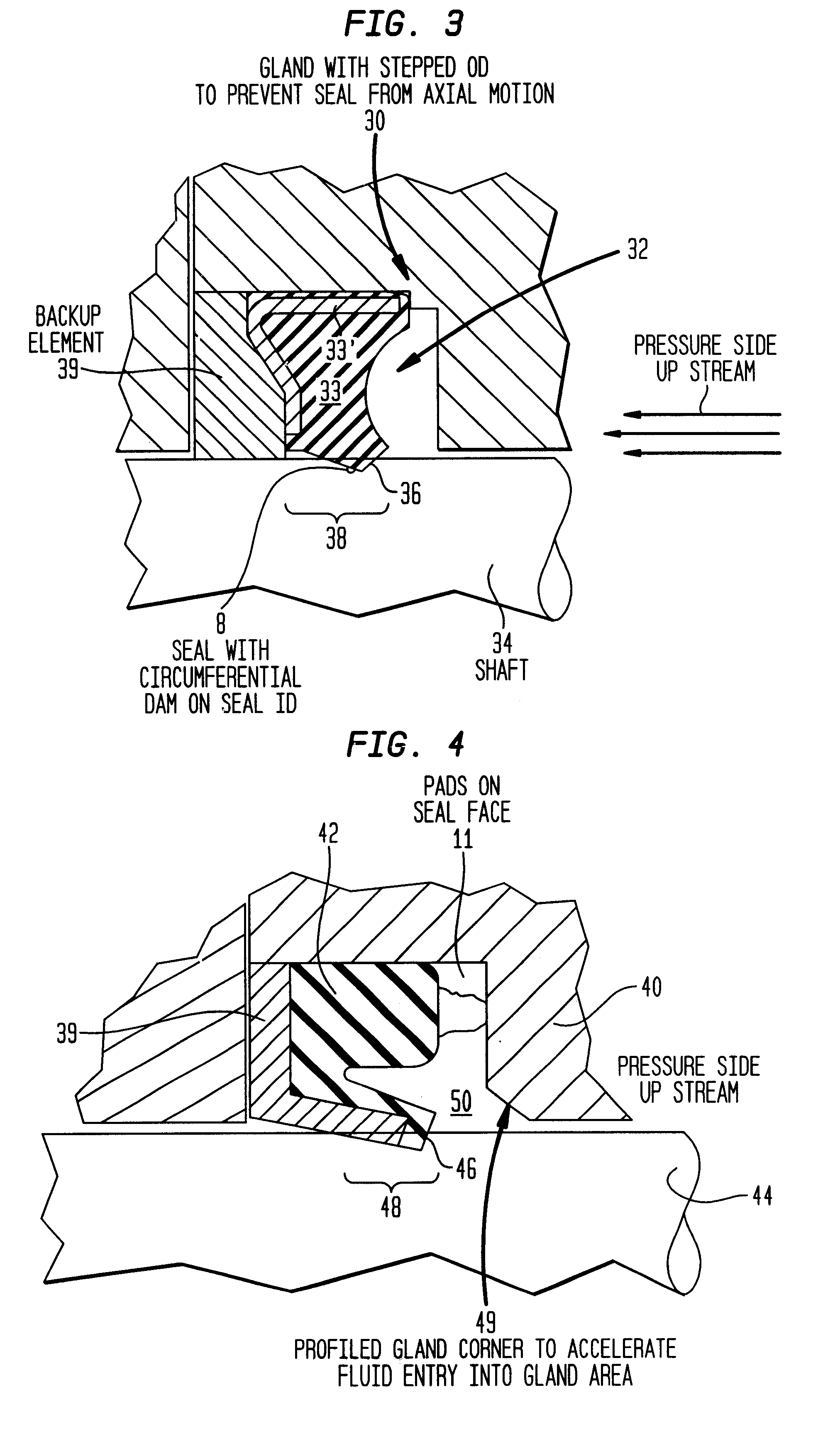
The system of this invention, for ease of explanation and understanding, is hereinafter described by means of explanation of the Figures which accompany this application and made part hereof. As above noted, each of FIGS. 1 & 2 illustrate a retention gland and seal geometry of two prior art configurations. Each of these configurations is deficient in one or more material respects where the seal is to be subjected to high fluid pressures or surges in fluid pressures. More specifically, FIG. 1 illustrates a combination of an open retention gland (10) and rotary seal (12) which are ineffective to resist lifting or displacement of the seal (12) from the rotary shaft (14) under hydraulic pressure (arrows indicate direction of fluid pressure) upon such seal. Similarly, FIG. 2 illustrates a combination of a closed retention gland (10') and seal geometry which is also ineffective to prevent the axial movement and lifting or displacement of the seal (12) from the rotary shaft (14) under pres...


PUM


Abstract

A rotary shaft sealing system comprising a rotary lip seal and its associated retention gland, wherein the each of the seal and the gland are complimentary of the other within the environment of use. The system is particularly adapted for the sealing of a rotary shaft in an environment wherein the hydraulic pressure upon the fluid within the gland is at least 20 psi, or higher; and, such fluid pressure within the gland is further subject to variation or surges at the time of start-up and/or during operation/use of the rotary shaft. The retention gland geometry assists in the direction and application of hydraulic pressure against the seal so as to increase the radial contact force between the seal lip and the rotary shaft, thus, insuring more complete and effective sealing at this contact interface. The seal of this system is preferable pre-loaded so as to apply positive sealing pressure against the rotary shaft both prior to and during use. In another of the preferred embodiments of this invention, the rotary seal is a composite of dissimilar materials, or comprised of similar materials, wherein the physical properties of each of the components of the composite enhance mechanical resistance of the composite to distortion and resistance to axial movement relative to the rotary shaft.

Description

1. Field of the Invention--This invention relates to an article of manufacture and method. More specifically, this invention relates to a system, incorporating a unique retaining gland and seal design, for rotary shaft sealing and to a method for sealing a rotary shaft. The system of this invention is suitable for high pressure sealing applications, specifically, for sealing of the rotary shaft of pumps and motor seals for automotive, marine, agricultural and industrial applications.2. Description of the Prior Art--Cartridge rotary seals have been used for many / years in a variety of applications for the sealing of various types of fluids and gases. The function and purpose of such seals includes containment of fluids (lubricants) within the internal environment associated with a rotary shaft, and the exclusion of foreign matter from the external environment from contamination of such lubricants.Generally, these seals comprise a solid elastomeric / flexible body supported in metal (ret...

Claims


Application Information

Patent Timeline
Patent Type & Authority Patents(United States)
IPC IPC(8): F16J15/16F16J15/32
CPCF16J15/166F16J15/3216F16J15/322
Inventor ULRICH, DON
Owner ULRICH DONALD
Why Eureka
Try Eureka