Check patentability & draft patents in minutes with Patsnap Eureka AI!

Gas feeding system for chemical vapor deposition reactor and method of controlling the same

a technology of chemical vapor deposition and gas feeding system, which is applied in the direction of chemically reactive gases, coatings, crystal growth process, etc., can solve the problems of process disadvantages such as the waste of non-use and idling gaseous reactant sources, and the impact of film thickness, film quality, and impurity concentration

Inactive Publication Date: 2002-08-13
ASM KOREA LTD
View PDF6 Cites 33 Cited by
  • Summary
  • Abstract
  • Description
  • Claims
  • Application Information

AI Technical Summary

Benefits of technology

It is another object of the present invention to provide a gas feeding system for chemical vapor deposition reactor and method of controlling the same capable of preventing the waste of non-use and idling gaseous reactant sources when not feeding the sources into the reactor.
In order to accomplish the aforementioned objects, the present invention provides a gas feeding system for chemical vapor deposition reactor having at least one reactant source supply apparatus, the supply apparatus each comprising: a mass flow controller for controlling the flow rate of a carrier gas which carries a reactant source; a reservoir for containing the reactant source, the reservoir having inlet and outlet valves for controlling the flow of the carrier gas through the reservoir; a supply valve for controlling the mass flow of the reactant source carried by the carrier gas to the reactor; an evacuation valve disposed between the outlet valve and the supply valve, the evacuation valve evacuating the carrier gas or the reactant source toward a vacuum pump; and a pass valve disposed between the inlet valve and the outlet valve so that the carrier gas passing therethrough flows into the reactor or the evacuation valve, the pass valve stabilizing the carrier gas mass flow controller as well as preventing the leakage of the reactant source from the reservoir.
Preferably, the reactant source supply apparatus further comprises a first purge gas supply unit disposed between the supply valve and the reactor so as to prevent the backward flow of other reactant sources into the source supply apparatus upon deposition reaction. More preferably, the first purge gas supply unit further comprises a mass flow controller for controlling the flow of purge gas therethrough to a constant level.

Problems solved by technology

The films formed by the above processes have enhanced uniformity and quality, and minimized impurity concentration therein, However, the above processes have a disadvantage of the waste of non-use and idling gaseous reactant sources.
However, such processes also have disadvantages that uniformity in film thickness, film quality, and impurity concentration are considerably affected depending upon the flow direction, flow velocity, temperature, types of used reactant sources.

Method used


Image

  • Gas feeding system for chemical vapor deposition reactor and method of controlling the same
  • Gas feeding system for chemical vapor deposition reactor and method of controlling the same
  • Gas feeding system for chemical vapor deposition reactor and method of controlling the same

Examples


example 2

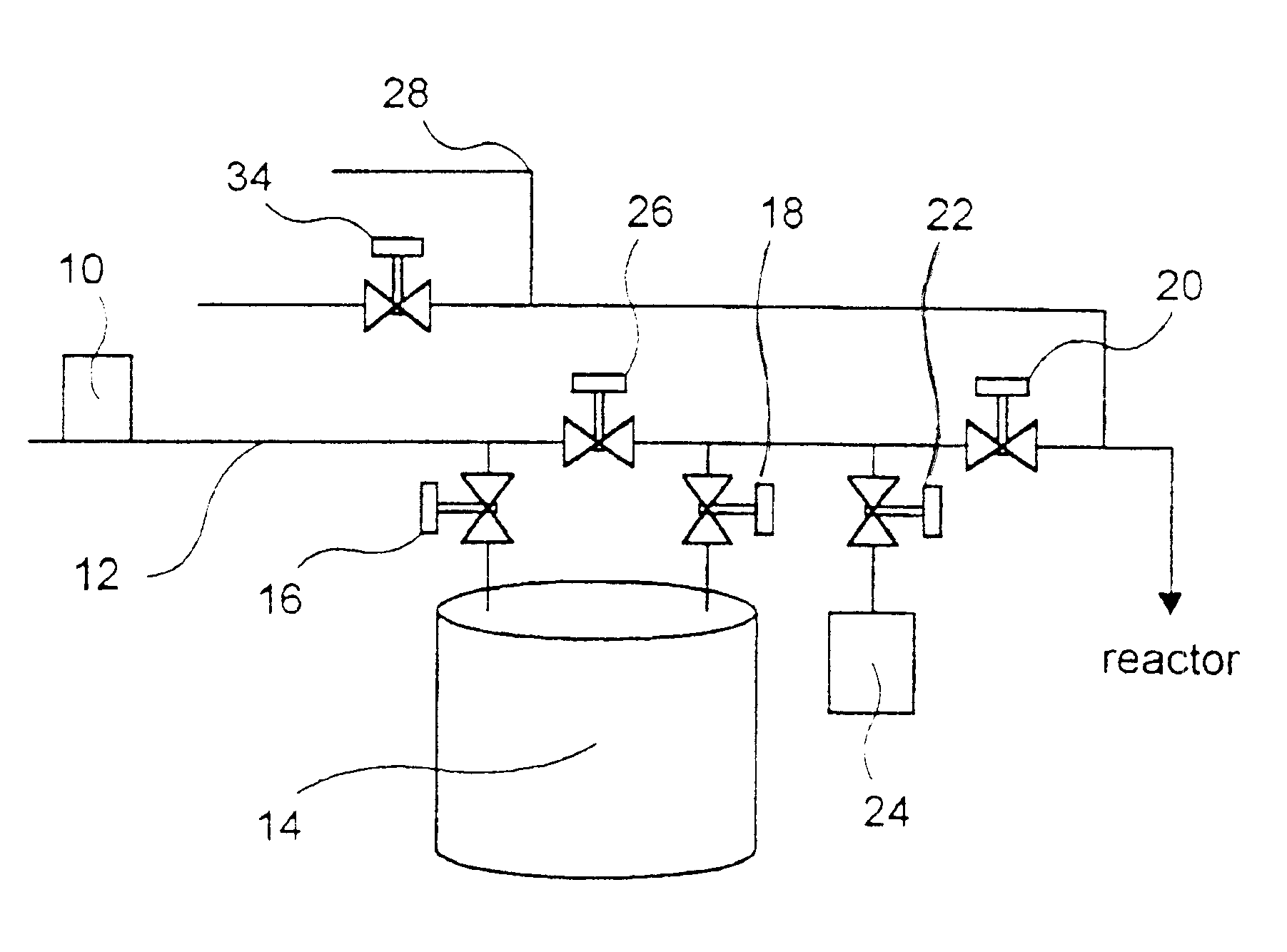
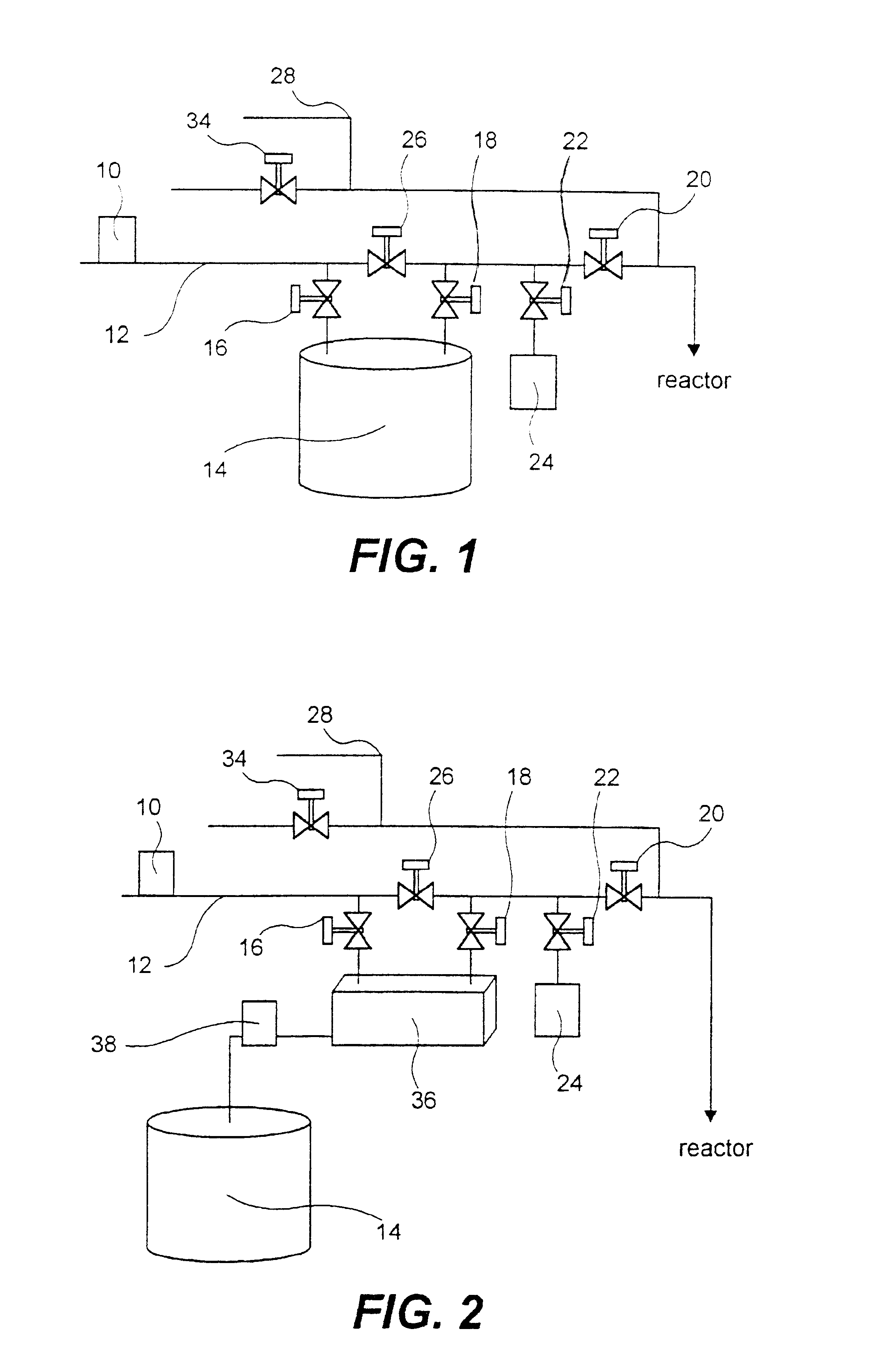
FIG. 2 is a schematic view of a gas feeding system, having a reactant source vaporizer, in accordance with another embodiment of the present invention. Referring to FIG. 2, the difference between the example 1 and the example 2 is that a vaporizer 36 for vaporizing the reactant source is disposed between the reactant source supply tube 12 and the reactant source reservoir 14. Moreover, a minute flow pump 38 is disposed between the reservoir 14 and the vaporizer 36 for the effective control of reactant source supply and its vaporization. The vaporizer 36 vaporizes the reactant source in liquid phase contained in the reservoir 14 beforehand to supply the reactant source into the reactor. The operation of other parts of the gas feeding system is the same as that of the example 1.

example 3

FIG. 3 is a schematic view of a gas feeding system with a plurality of reactant source supply apparatuses connected to one reactor, in accordance with another embodiment of the present invention. Referring to FIG. 3, two reactant source supply apparatuses B and C, each being the same as described in the example 1, are connected to one reactor. Additionally, a reactive gas supply apparatus A is connected to the reactor via a reactive gas supply tube 40. The flow of gas A to the reactor is regulated by a supply valve 20 disposed on the reactive gas supply tube 40. An evacuation valve for evacuating the gas A is indicated with reference numeral 22.

As is the same as the examples 1 and 2, each supply apparatus comprises a first purge gas supply unit 28 and a mass flow controller (not shown) for the purge gas to prevent the backward flow of other reactant sources from the reactor upon deposition reaction. Additionally, each supply apparatus comprises a second purge gas supply unit for pro...


PUM

PropertyMeasurementUnit
flow rateaaaaaaaaaa
mass flowaaaaaaaaaa
thicknessaaaaaaaaaa

Abstract

A gas feeding system for applications such as chemical vapor deposition (CVD) is provided. The gas feeding system comprises a plurality of reactant source supply apparatuses that are connected to a reactor to supply different reactant sources therein discontinuously or sequentially. The gas feeding system includes a pass valve that is disposed in a supply tube between inlet and outlet valves of the reservoir for containing the reactant source. With the pass valve, the carrier gas passing therethrough flows into the reactor or the evacuation valve without passing through the reservoir when the inlet valve and outlet valve are closed to prevent the waste of non-use reactant sources. With the present invention gas feeding system, the uniformity and quality of the deposited film can be improved and the waste of reactant source can be reduced.

Description

The present invention relates to a gas feeding system, and more particularly, to a gas feeding system for chemical vapor deposition (CVD) reactor capable of improving the uniformity and quality of deposited film in the manufacture of semiconductor devices. The present invention also relates to a method of controlling the same which prevents the waste of reactant source.It is often desirable to form films of uniform thickness on a substrate in semiconductor manufacturing. Accordingly, considerable efforts have been made to improve both equipment and manufacturing process.Recently, many processes for forming a high quality film were developed using surface reaction on a semiconductor substrate: processes such as using discontinuous supplies of a reactant source on a substrate, atomic layer epitaxy, and sequential supplies of a reactant sources on a substrate. The films formed by the above processes have enhanced uniformity and quality, and minimized impurity concentration therein, How...

Claims


Application Information

Patent Timeline
Patent Type & Authority Patents(United States)
IPC IPC(8): C23C16/455C23C16/448C30B25/14H01L21/205H01L21/31
CPCC23C16/4481C23C16/455C23C16/45561C30B25/14C23C16/52
Inventor LEE, KYU HONGKANG, WON GUKANG, SANG WON
Owner ASM KOREA LTD
Features
  • R&D
  • Intellectual Property
  • Life Sciences
  • Materials
  • Tech Scout
  • Unparalleled Data Quality
  • Higher Quality Content
  • 60% Fewer Hallucinations
Learn More