Raman-based utility optical amplifier

a utility optical amplifier and raman technology, applied in the direction of electromagnetic transmission, semiconductor laser arrangement, semiconductor laser, etc., can solve the problems of limited wdm increase capacity, general underutilized 1.3 .mu.m portion of bandwidth, and inability to provide a useful amount of gain for optical signals having a wavelength of about 1.3 .mu.m

Inactive Publication Date: 2002-08-13
JDS UNIPHASE CORP
View PDF20 Cites 69 Cited by
  • Summary
  • Abstract
  • Description
  • Claims
  • Application Information

AI Technical Summary

Problems solved by technology

In many practical communication systems, however, the increase in capacity achieved by WDM is restricted by the fact many optical amplifiers can provide gain within only a fairly narrow bandwidth.
An EDFA can provide reasonable gain for optical signals having a wavelength of about 1.5 .mu.m but it cannot provide a useful amount of gain for optical signals having a wavelength of about 1.3 .mu.m.
As a result, the 1.3 .mu.m portion of the bandwidth is generally underutilized in optical communication systems that incorporate EDFA.
This is particularly unfortunate in systems that use silica fiber because signal losses in such fiber are usually lower for wavelengths at 1.3 .mu.m than they are for wavelengths at 1.5 .mu.m.
Unfortunately, a Raman amplifier can be noisier than many other types of optical amplifiers like an EDFA, for

Method used


Image

  • Raman-based utility optical amplifier
  • Raman-based utility optical amplifier
  • Raman-based utility optical amplifier

Examples


Embodiment Construction

A. Overview

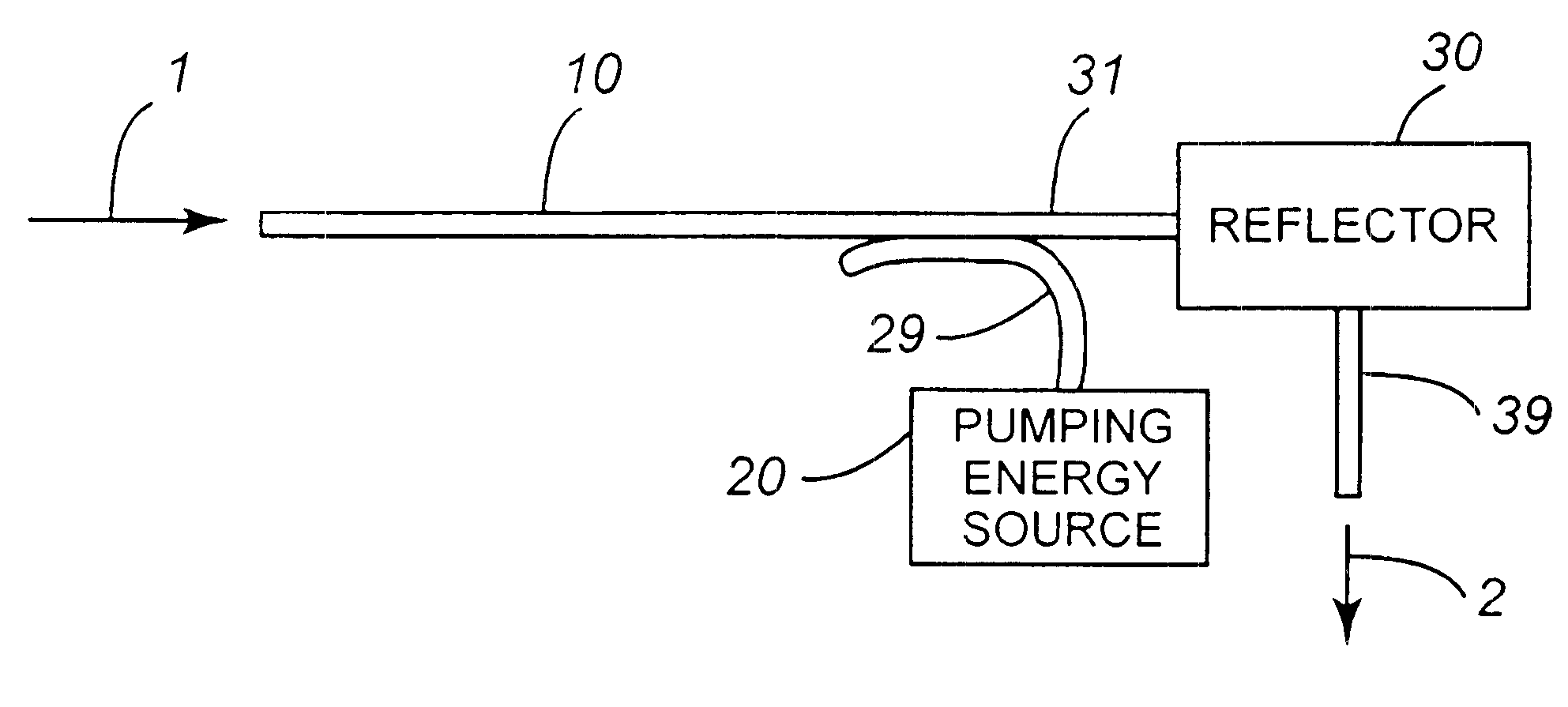
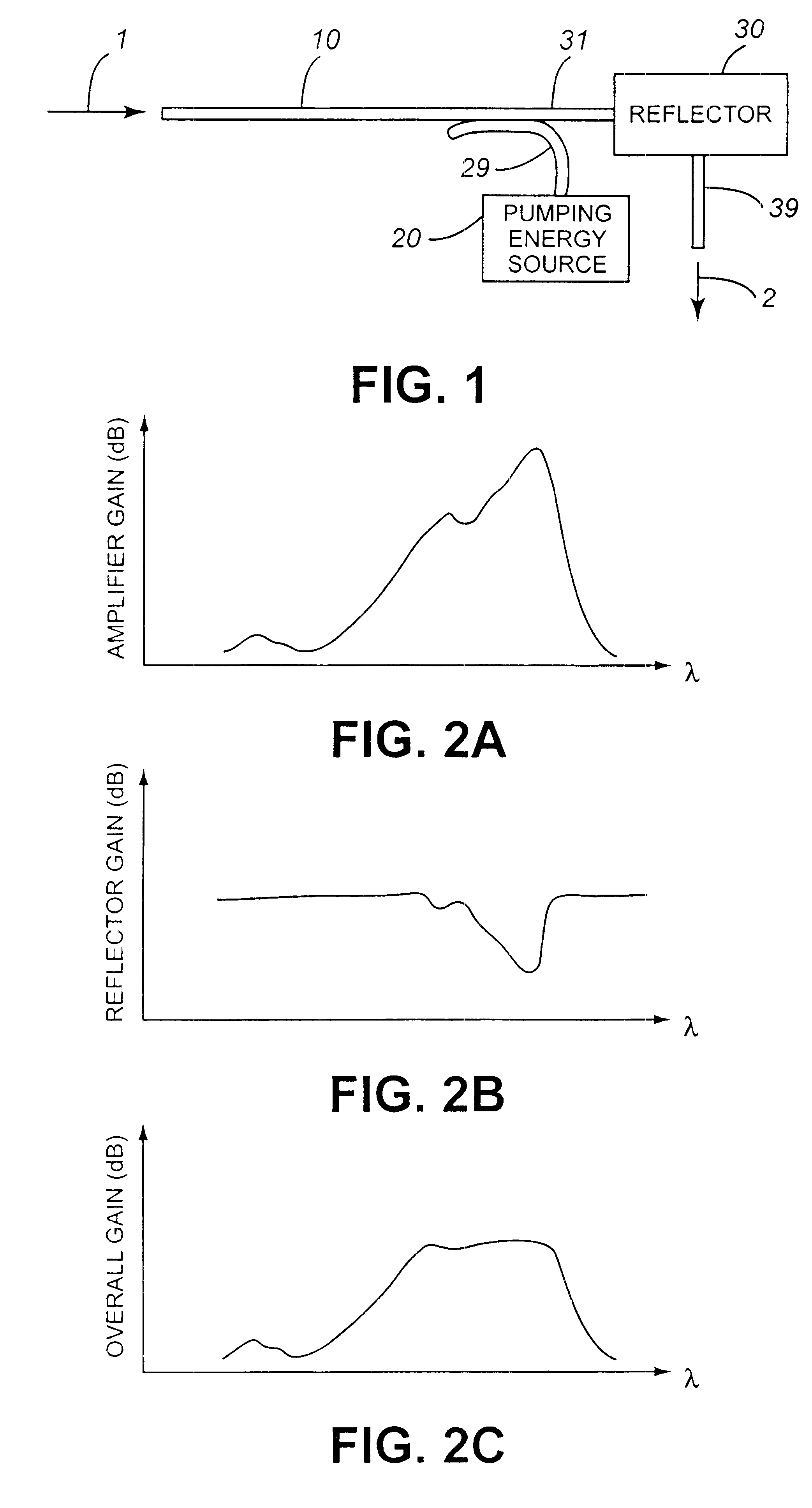
A block diagram of an optical amplifier according to the present invention is illustrated in FIG. 1. In this implementation, an optical signal 1 to be amplified is received through a first end of optical waveguide 10. No particular type of waveguide is critical. In preferred implementations, optical waveguide 10 is a silica optical fiber according to any one of a number of conventional designs. Optical signal 1 is amplified by Raman amplification as it propagates from the first end toward a second end of optical waveguide 10.

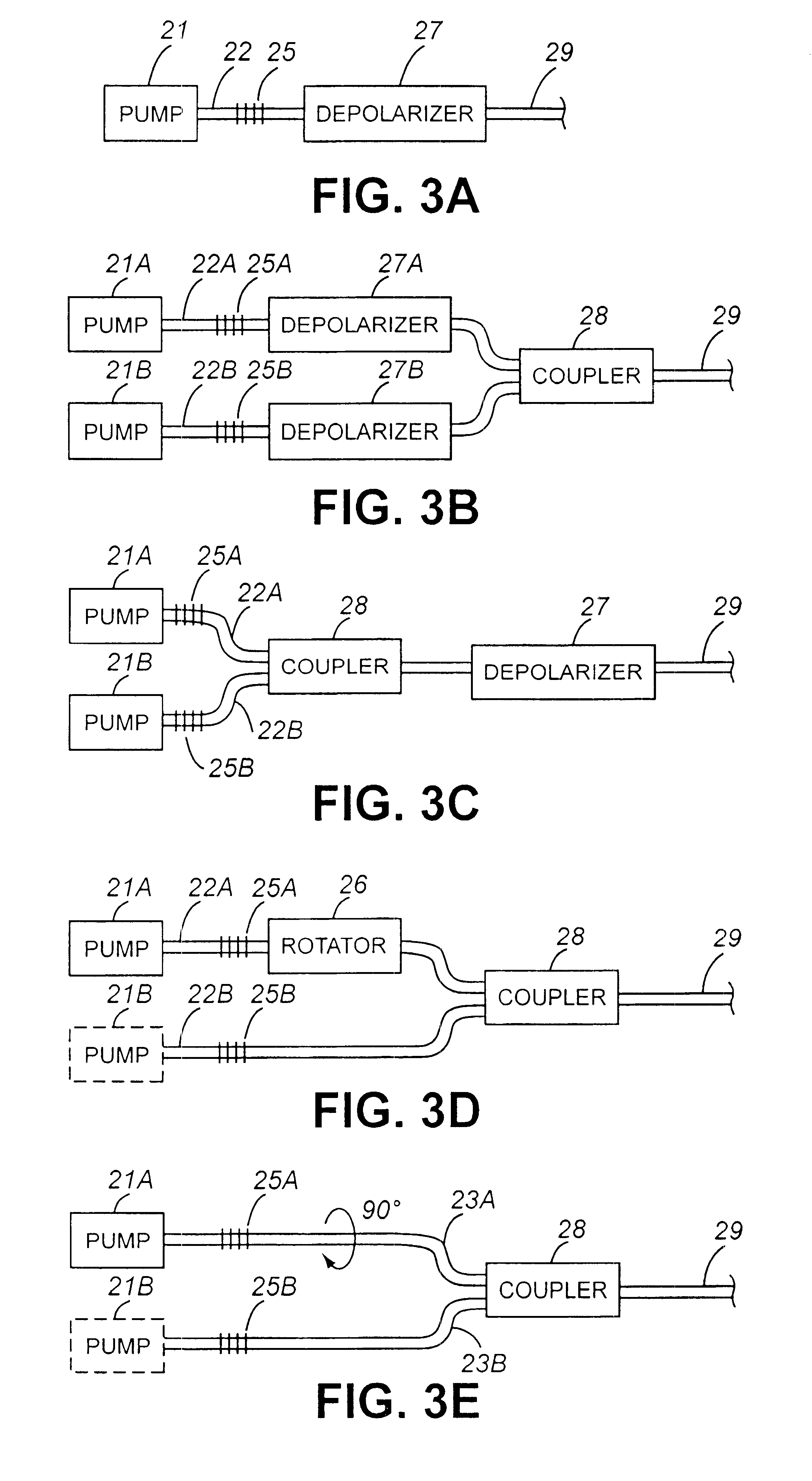
Optical waveguide 10 receives pumping energy from pumping-energy source 20 through optical waveguide 29. This pumping energy causes the Raman amplification occurring in optical waveguide 10 to have a particular spectral gain characteristic. Various implementations of pumping-energy source 20 are discussed below.

Reflector 30 receives an amplified optical signal through input waveguide 31 coupled to the second end of optical waveguide 10, and reflects t...


PUM


Abstract

An optical amplifier with a flattened wideband response is obtained by coupling counter-propagating pumping energy into an optical waveguide to cause Raman amplification in the optical waveguide, and by reflecting an amplified signal received from the optical waveguide into an output waveguide using a reflector having a spectral characteristic that is complementary to the spectral gain characteristic of the Raman amplification.

Description

The present invention pertains generally to optical communication devices and pertains more particularly to optical waveguides that provide Raman amplification.Current telecommunication and computer network services demand high-capacity communication systems. This demand is often satisfied by optical communication systems in which voice and data signals, represented by optical signals, are conveyed through optical waveguides such as silica fibers. Many optical communication systems are able to achieve better performance by using one or more types of optical amplifiers to increase the intensity of the optical signals. Typically, these optical amplifiers are driven by a source of optical energy known as pumping energy.The demand for communication system bandwidth is growing rapidly. One technique known as wavelength division multiplexing (WDM) is often used in optical communication systems to meet this growing demand in a cost-effective manner by more fully utilizing the capacity of e...

Claims


Application Information

Patent Timeline
IPC IPC(8): H01S3/094H01S5/40H01S3/00H01S5/14H01S5/065H01S5/00H01S3/30H01S3/0941H01S5/022H01S5/062
CPCH01S3/005H01S3/094003H01S5/146H01S5/4025H01S3/0078H01S3/094073H01S3/09415H01S3/302H01S5/1096H01S2301/04
Inventor WELCH, DAVID F.LANG, ROBERT J.VAIL, EDWARD C.ZIARI, MEHRDAD
Owner JDS UNIPHASE CORP
Why Eureka
Try Eureka