
Display and input device and display and input system

Inactive Publication Date: 2002-08-20
IDEC CORPORATION
View PDF14 Cites 50 Cited by
  • Summary
  • Abstract
  • Description
  • Claims
  • Application Information

AI Technical Summary

Benefits of technology

It is a first object of the present invention to provide a display and input device providing switch operating means on a display while maintaining operation feeling of a switch operation and implementing no existence of an opaque part of the switch operating means on the display, for consequently implementing excellent operating environment which can manage both with improvement of reliability of the switch operation and effective use of the display.
According to the present invention, the transparent member of the switch operating means exists on the display, whereby the user can readily recognize the association between the menus which is the representation of the switch operating means and the actual switch operating means. Thus, erroneous input can be prevented.
In the preferred embodiments of the present invention, the switch operating means has operation feeling such as stroke feeling or click feeding, and excellent operating environment can be obtained.
The present invention is further directed to a portable display and input device having such switch operating means, which is excellent in operability.

Problems solved by technology

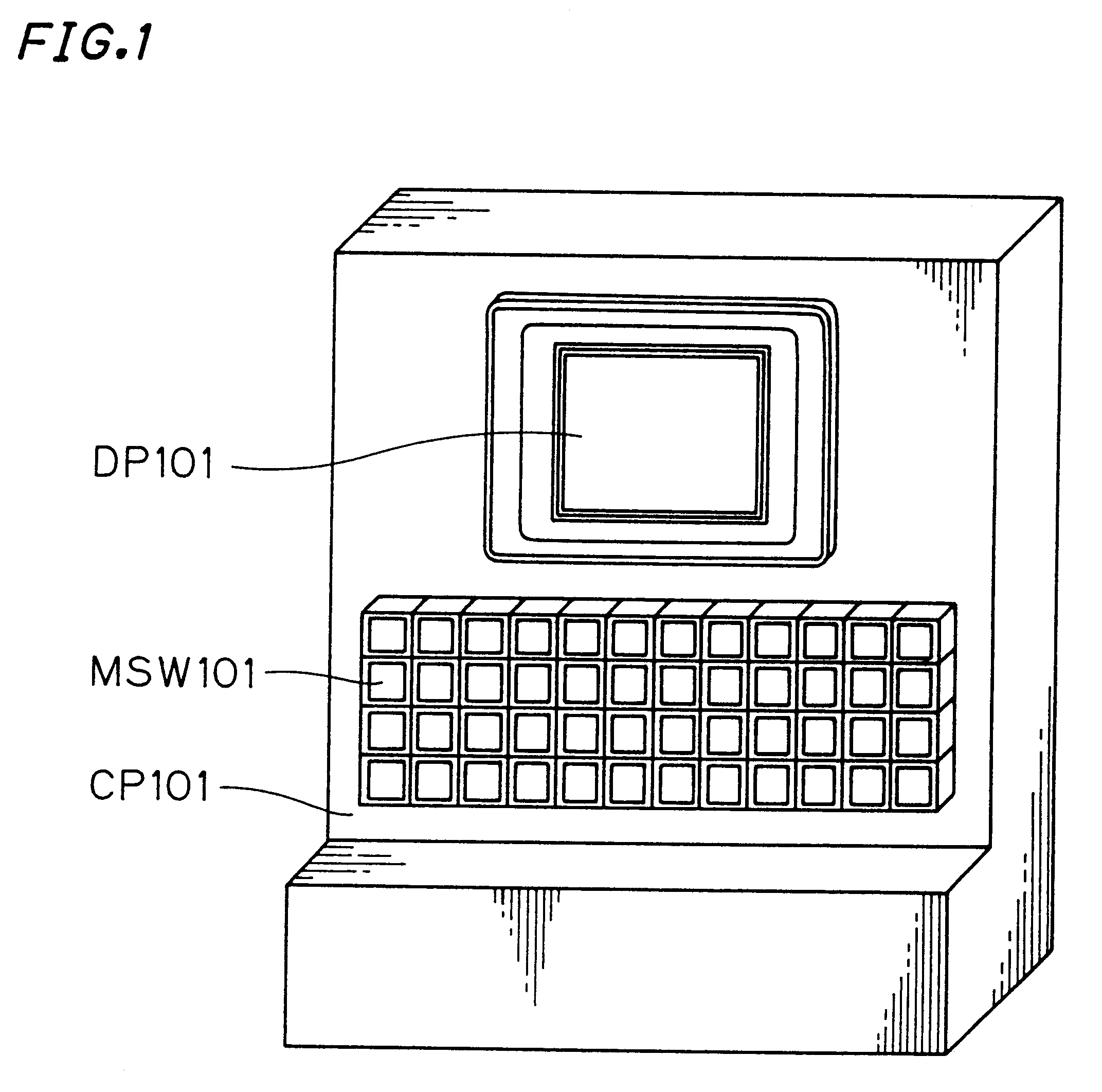
However, the display and input device having such a mode has such problems that it is hard for the user to recognize the association between the displayed information and the switch operating means MSW101 since the display DP101 and the switch operating means MSW101 are separate from each other and there is a high possibility of making erroneous input through a "feeling operation" of performing the operation only with the feeling of his fingers without observing the switch operating means MSW101.
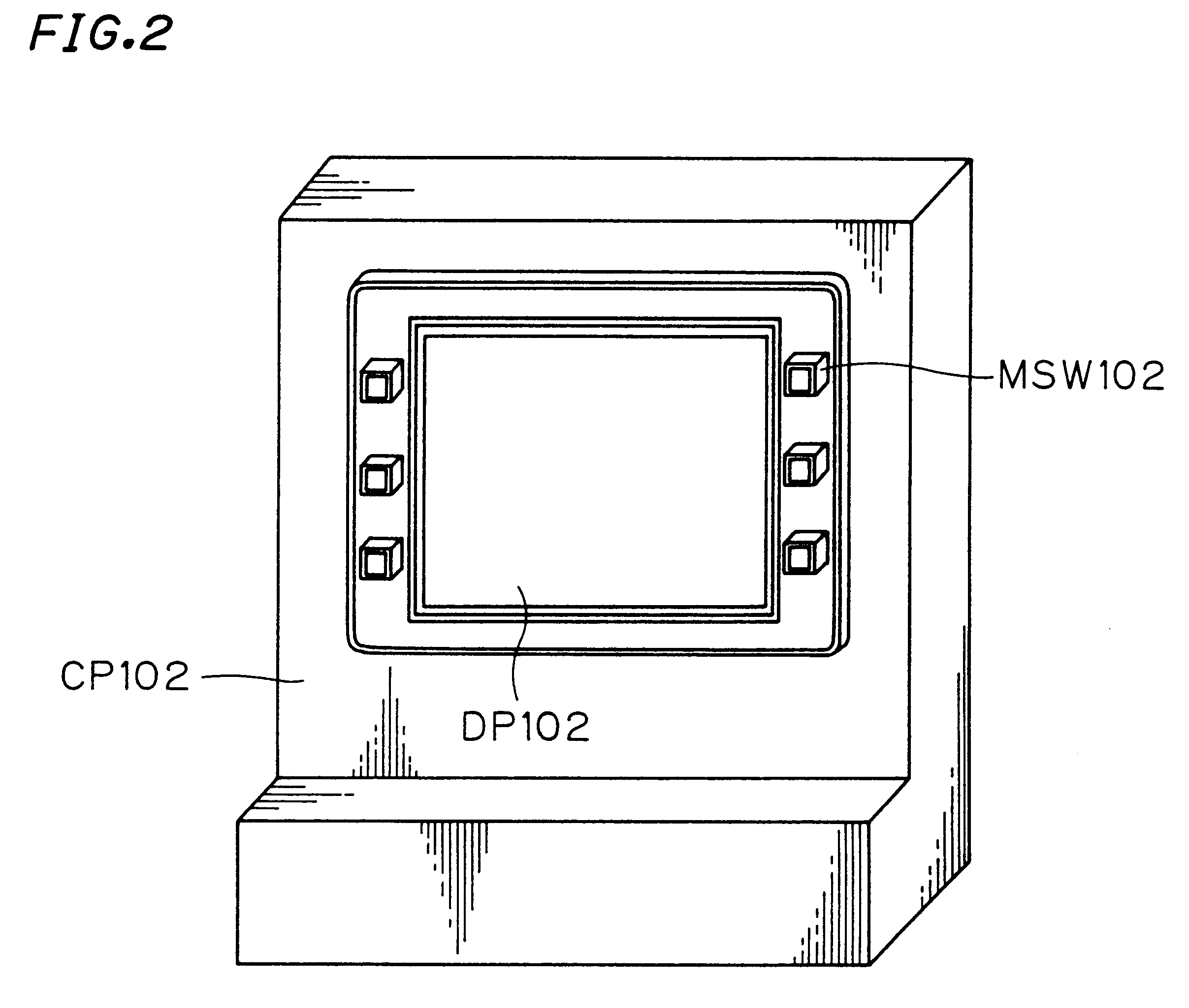
When the representation on the display DP102 and the switch operating means MSW102 are thus arranged, it follows that the user performs an unnatural operation of pushing the switch operating means MSW102 without observing the same since the representation on the display DP102 and the representation on the positions of the switch operating means MSW102 do not completely match with each other, so the tendency of pushing the switch operating means MSW102 without observing the display DP102 intensifies, and the tendency of performing a feeling operation further increases, leading to deterioration the reliability of the operation.
When using a touch switch or the like as the switch operating means on the display, visual confirmation of the switch is indeed easy to perform but the touch switch, hardly having the amount of movement of a switch operation and hence failing to provide the same feeling of pushing, is usually repeatedly pushed.
Since, a touch switch does not have the same amount of movement of a mechanical switch further, it cannot cope with a human-unique motion of stopping the switch operation halfway, and therefore has a problem that information input is performed if a switch display part is slightly touched.
When simply arranging mechanical switch operating means on a display, it follows that an opaque part specific to the switch operation means exists on the display and hence there arises a problem that the representation is extremely hard to observe for the user.
When the opaque part exists on the display, further, the displaying mode of the display is so limited that no image can be displayed on the overall surface of the display, for example, and the overall representation cannot be effectively utilized.

Method used


Image

  • Display and input device and display and input system
  • Display and input device and display and input system
  • Display and input device and display and input system

Examples


first embodiment

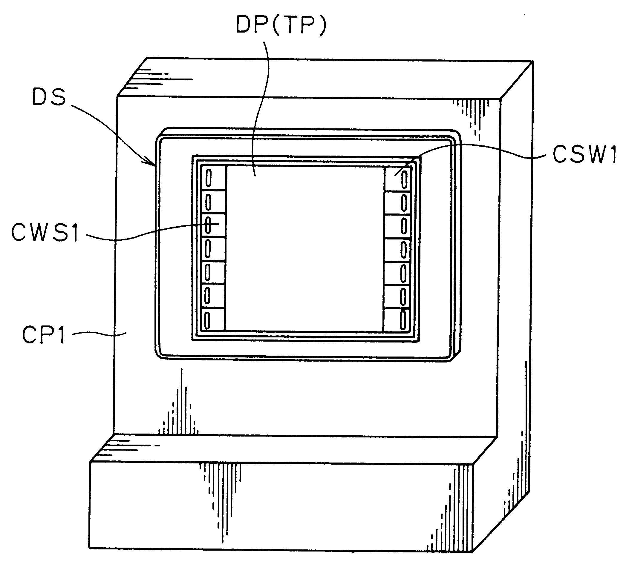
FIG. 4 is a diagram showing an FA controller CP1 which is a first embodiment of the display and input device according to the present invention. This controller CP1 has transparent switch operating means CSW1 on a display DP formed by a liquid crystal display panel, so that information is selected by pushing this switch operating means

FIG. 5 is a diagram showing a display part DS of this controller CP1. The transparent switch operating means CSW1 are plurally provided on left and right peripheral edge portions on the display DP as illustrated, and in members forming the switch operating means CSW1, all parts overlapping on the display DP are formed by transparent members. Further, opaque members inevitable as elements of the switch operating means CS1 are arranged to be hidden in areas E shown by broken lines outside the display DP. In the strict sense, the opaque members are not restricted to outside the display DP but arranged outside a displaying area on the display DP, while it ...

second embodiment

While the display and input device employing the switch operating means CSW1 utilizing the magnets has been described with reference to the first embodiment, this switch operating means may be that utilizing other than magnets. FIG. 15 and FIG. 16 are diagrams showing a section of switch operating means CSW2 utilizing an opaque mechanical switch 113b such as a tactile switch having a mechanical mechanism, and the appearance of the device is absolutely similar to that of the first embodiment shown in FIG. 4 and FIG. 5.

This switch operating means CSW2 is formed by a switch operating body 111 depressed with a finger FG, a transparent protective cover 112 and an engaging member 116b holding the switch operating body 111 and the mechanical switch 113b and is directly provided on a display DP formed by a liquid crystal display panel, and hence no touch switch TP is provided on the display DP dissimilarly to the first embodiment.

While the switch operating body 111 is held by the protective...

third embodiment

FIG. 19 and FIG. 20 are appearance diagrams showing a portable display and input terminal CP2 which is a third embodiment according to the display and input device of the present invention. FIG. 19 is a perspective view as viewed from a display DP side, and FIG. 20 is a perspective view of a rear surface as viewed from arrow B in FIG. 19.

In a display part DS of this display and input terminal CP2, a resistor film touch switch TP is provided on a display DP formed by a liquid crystal display panel similarly to the first embodiment, and switch operating means CSW1 utilizing magnets are provided on left and right edges on the display DP. The remaining elements such as the input control means 103, the image changing means 104, the display control means 105 and the like shown in FIG. 12 may be stored in a cover 106, or may be provided outside the terminal CP2.

In the case of such a display and input device having portability, such excellent operating environment is implemented that an inp...


PUM


Abstract

In a display and input device (CP) displaying information on a display (DP) and performing changing of the information and communication through switch operating means (CSW1), the switch operating means (CSW1) are arranged on the left and right edges of the display (DP), opaque members among members forming the switch operating means (CSW1) are arranged outside the screen of the display (DP), and only transparent members are arranged on the display (DP). Thus, a switch operation can be performed while recognizing functions of the switch operating means (CSW1) and the switch operating means (CSW1) having the stroke feeling and click feeling of a mechanical switch so that an operating environment having excellent operability and implementing reliable input can be obtained.

Description

The present invention relates to a display and input device such as an FA controller or a notebook loaded with an arithmetic processing mechanism having a display such as a cathode-ray tube or a liquid crystal display panel and input means such as switch operating means attached thereto and a display and input system.As a display and input device having a display and input means for changing representation on the display or performing an input operation to another device on the basis of information inputted through the operation input means, there is an electronic notebook loaded with an arithmetic processing mechanism, an FA controller or the like. It can be said that a personal computer system or the like having a display is also a display and input device having a display capable of variable display and switch operating means such as a keyboard which is input means.FIG. 1 is a diagram showing an FA controller CP101 operating a robot or the like as an exemplary display and input d...

Claims


Application Information

Patent Timeline
IPC IPC(8): G06F1/16G06F3/033G06F3/023G06F3/048
CPCG06F1/1601G06F3/04886G06F3/0489H03M11/26
Inventor TSUJI, YOSHITAKAKAWAKAMI, MASAHIKONISHIKI, TOMONORIFUJITA, TOSHIHIROOKAMOTO, AKITOHASEGAWA, HIROMASALI, HONGGUANGOGINO, SHIGETO
Owner IDEC CORPORATION
Learn More