
Method and apparatus for measuring optical aberrations of the human eye
a technology of optical aberration and human eye, applied in the field of human eye optical aberration measurement method and apparatus, can solve the problems of less than optimal images generated, complex systems, and high cost of optical potential maximization of visual systems
Patent Information
- Authority / Receiving Office
- US · United States
- Patent Type
- Patents(United States)
- Current Assignee / Owner
- Publication Date
- 2002-08-27
- Estimated Expiration
- Not applicable · inactive patent
Smart Images
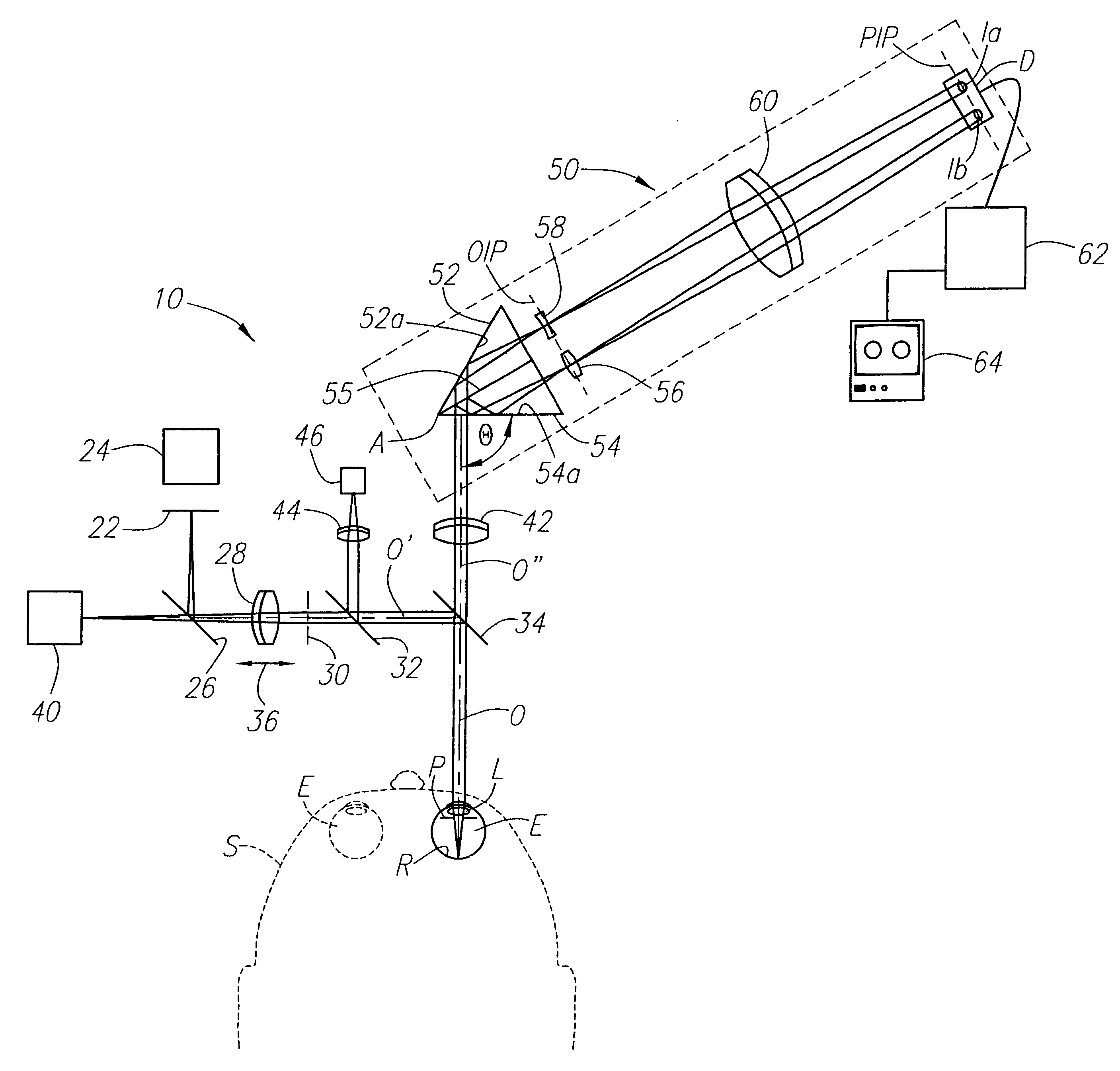
Figure 1 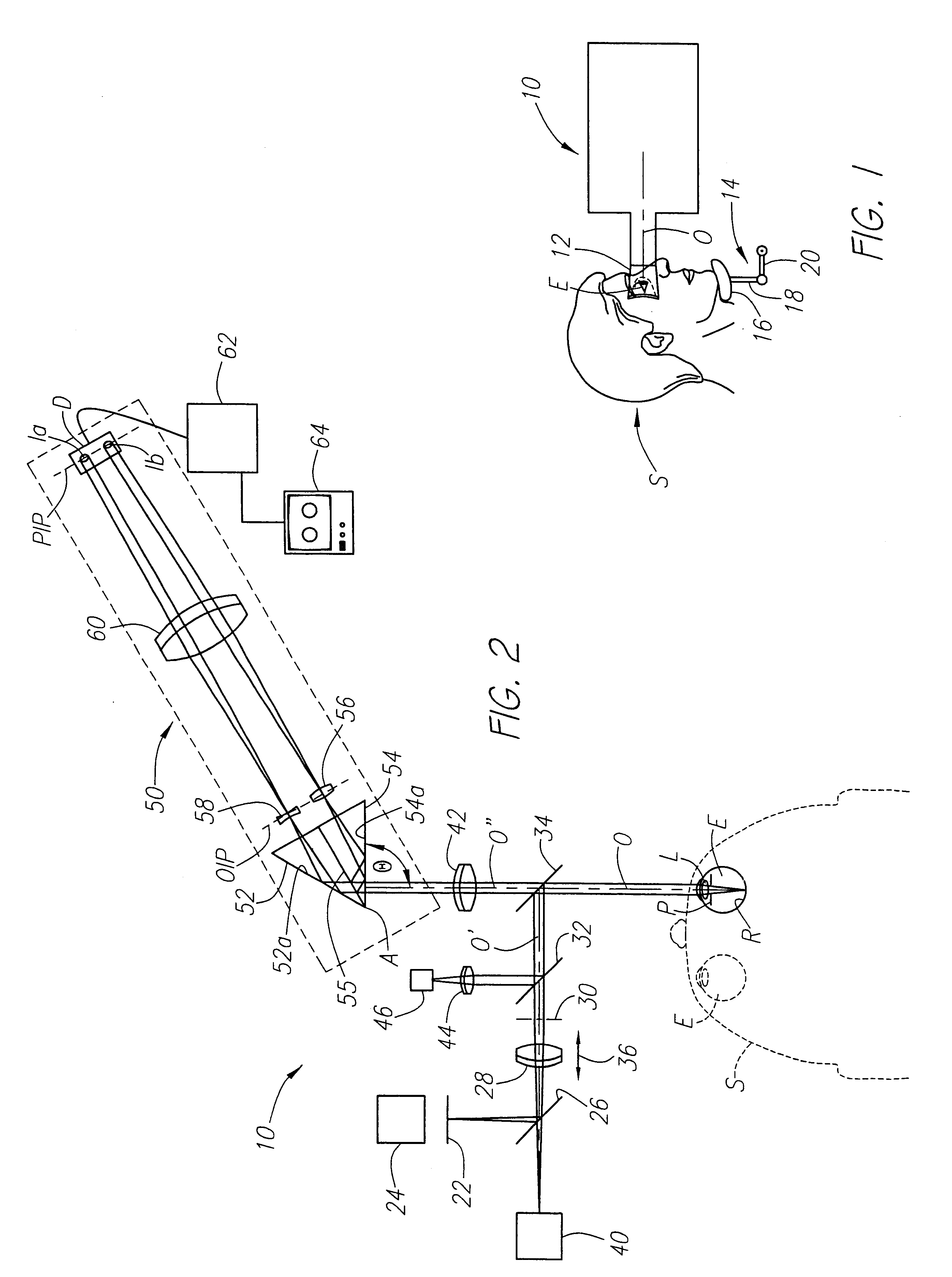
Figure 2 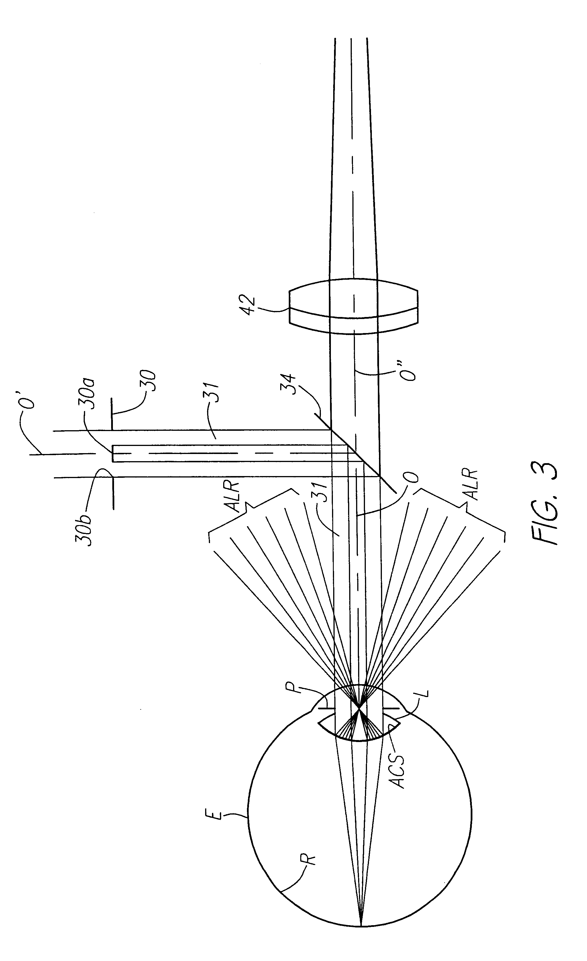
Figure 3
Abstract
Description
The present invention relates to methods and optical instrumentation for objectively measuring the aberrations of the human eye and specifically to an instrument capable of measuring not only the focus (spherical) and astigmatism (cylindrical) characteristics and aberrations of a person's eye but also all of the lower and higher order optical aberrations that are derived from a measured wavefront utilizing a wavefront curvature sensor.Measuring the aberrations of an optical system, including a human eye, is an important part of working with any optical system. Existing methods of measurement include various interferometric techniques, the Shack-Hartman wavefront sensor, and various systems involving the projection of patterns through the optical system. These systems are typically complex and expensive and most require access to the focal plane.The human eye, although comprised of only a few optical components, may manifest a wide variety of optical aberrations that vary from person...
Examples
Embodiment Construction
Referring now to FIGS. 1 and 2, the subject person S that is to have his or her eyes analyzed by the optical apparatus, generally designated 10, of the present invention positions one eye against a flexible eye cup 12 for aligning the center of the pupil of that eye with the optical axis O of the apparatus 10. Preferably, the head of the subject person S is adjusted to obtain that alignment and then supported in that position by any convenient means, such as an adjustable chin support 14. For example, a shaped pad 16 may be supported by a pair of pivotally connected links 18 and 20 that can be manipulated and then locked in position when the subject person S has his or her eye E in appropriate alignment with the optical axis O, which alignment can be determined by the operator of the apparatus in a manner described below. For clarity of illustration, the eye cup 12 is omitted from the schematic plan view FIG. 2.
Referring more particularly to FIG. 2, the optical apparatus 10 is provi...