Method of reducing axial beam focusing

a beam focusing and axial beam technology, applied in the direction of plasma, reactive propulsion thrust device, electrical apparatus, etc., can solve the problems of reducing the axial beam focusing efficiency, so as to reduce the size of the magnet system, good vacuum pumping conductance, and good vacuum pumping efficiency

Inactive Publication Date: 2002-09-03
GEMS PET SYST
View PDF4 Cites 12 Cited by
  • Summary
  • Abstract
  • Description
  • Claims
  • Application Information

AI Technical Summary

Benefits of technology

A method is disclosed for minimising the size of the magnet system and especially the diameter of the magnet poles of a cyclotron system for production of radioactive tracers. The method and a cyclotron according to the method make use of an operation mode having v.sub.z well below the critical resonance value of v.sub.z =1 / 2. Firstly, the sector gap is fixed at a small value (typically 15-30 mm) giving relatively few ampere-turns. Secondly, the valley pole gap is fixed at a value large enough to give good vacuum pumping conductance and to house a narrow spaced RF electrode system with acceptable capacitance and power consumption. For medium field strengths the value of v.sub.z will now be lower than v.sub.z =1 / 2 but still too close. The method now involves the step of raising the ampere-turns / coil current such that the sector field becomes greater than the saturation value for soft steel, which is approximately 2.15 Tesla. This will have two desirable effects on the value of v.sub.z :

Problems solved by technology

Firstly, there will be a reduced conductance in the pole gap for vacuum pumping and secondly there will be very little space for the RF acceleration electrodes.
The nature of the first effect refers to the fact that reduced opening areas has a negative effect on the vacuum pumping conductance leading to deterioration of the vacuum.
A lower vacuum conductance leads to higher amounts of rest gasses, thus resulting in higher beam losses and vice versa.
However, as already noted above, if the valley gap gets too large, the magnetic field strength in the valley gets too small relative to the sector field strength and the axial beam focusing as expressed by v.sub.z (number of axial ion beam oscillations per orbit revolution) will increase and eventually get into the v.sub.z =1 / 2 resonance which prohibits stable beam acceleration.
The first choice results in a compact magnet but a design with too small valley gaps to satisfy the demands of a low power RF system and a satisfactory vacuum conductance while the other choice results in too large a magnet in order to fulfil the size requirements.
The best average design option for a compact cyclotron magnet seems to be obsolete due to the restrictions related to axial focusing.

Method used


Image

  • Method of reducing axial beam focusing
  • Method of reducing axial beam focusing
  • Method of reducing axial beam focusing

Examples


Embodiment Construction

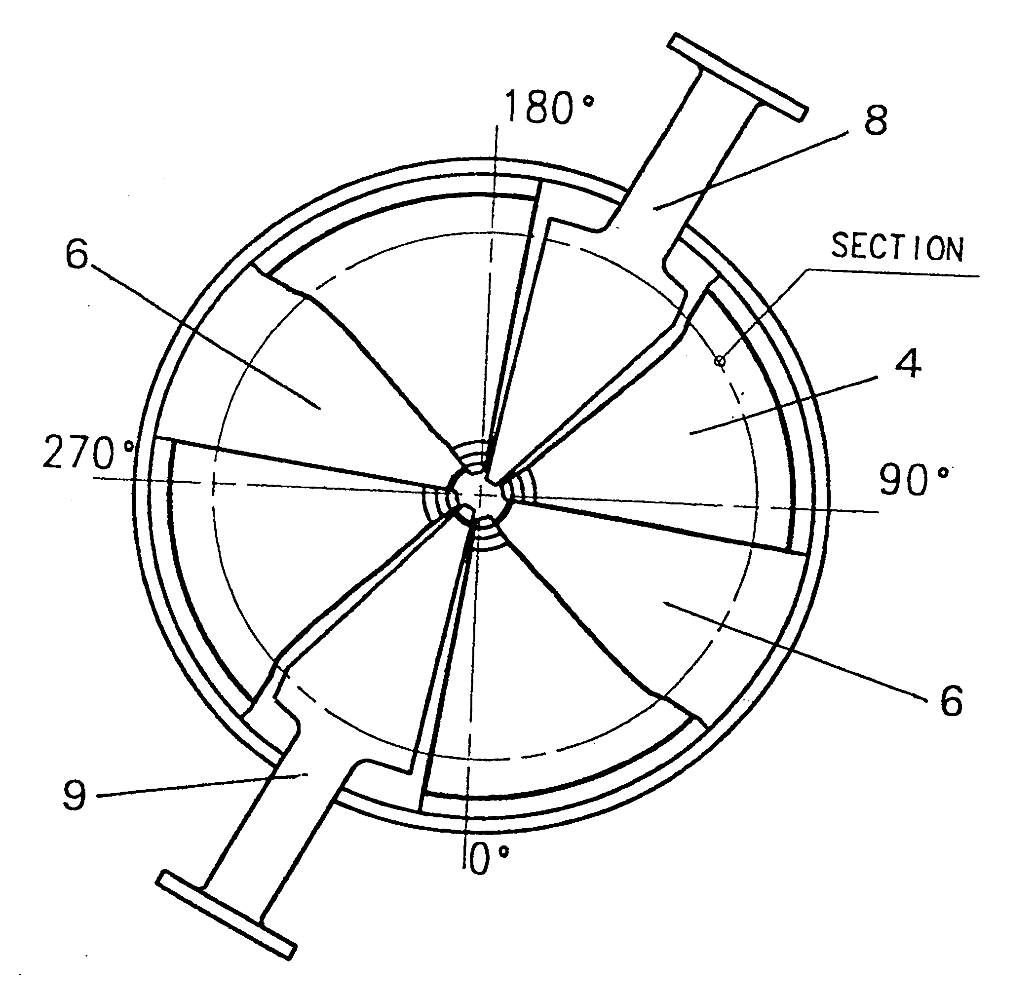
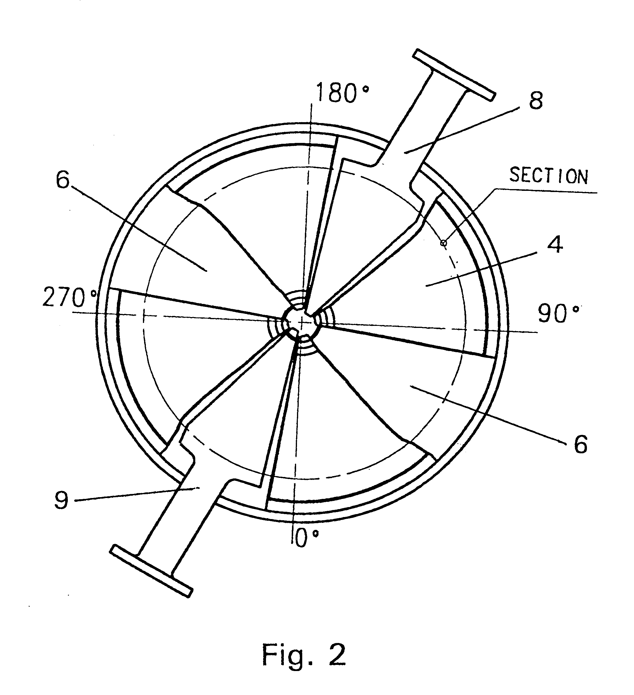
According to the present inventive improvements, a cyclotron device being applicable for a PET Isotope Production facility is disclosed. The device according to the present invention takes into account opposing parameters thereby facilitating a very compact design. This design will commonly be referred to as the "MINItrace" device. The MINItrace device at the same time also constitutes an Integrated Radiation Shield for a PET isotope production system for creating short lived radioactive tracers used in medical diagnostics.

However, the MINItrace compact magnet design is based on a v.sub.z value below 0.5 but still with satisfactory space for the RF electrodes and good vacuum conductance. A system according to this new concept will be described below:

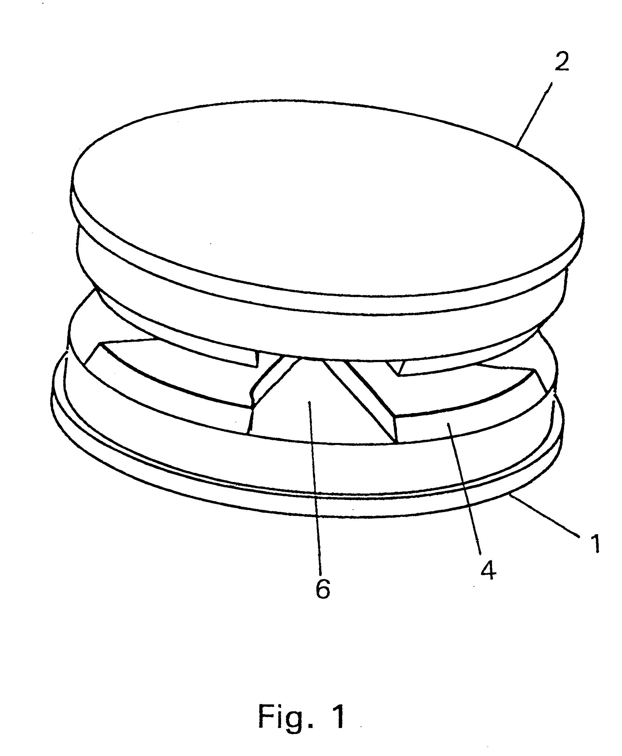
FIG. 1 illustrates a pair of magnet poles, a first magnet pole 1 and a second magnet pole 2 for use in a cyclotron according to an illustrative embodiment of the present invention. Both magnet poles present the same number of sectors 4, ...


PUM


Abstract

A method is disclosed for minimising the diameter of the magnet poles of a cyclotron system for production of radioactive tracers. The method selects an operation mode having vz defined below the critical resonance value of vz=½ and chooses a valley technique having shallow valleys by selecting a first magnet pole parameter defining a valley gap accepting a narrow spaced RF electrode system and size facilitating a vacuum conductance necessary for obtaining a low enough pressure. The method then defines a second magnet pole parameter by setting a sector gap size. The magnetic azimuthal field shape is transformed from being "square-wave"-shaped to becoming approximately sinusoidal by increasing the magnetising field. Then an average magnetic field is calculated from the increased magnetising field and the first and second magnet pole parameter. A pole diameter can then be established to obtain a most compact design of the electromagnet for a cyclotron system. A cyclotron system in accordance with the method is also disclosed.

Description

The present invention relates to a method and system for minimising the magnet size in a cyclotron.Production of radioisotopes normally takes place by means of a suitable particle accelerator, for instance a cyclotron, in which an ion beam (i.e., a beam of charged particles) is accelerated. The radioisotopes are formed via nuclear reactions between an incident ion beam and a target medium, which can be a pressurised gas, a liquid or a solid.Cyclotrons make use of a magnetic field for deflection of accelerated ions into circular orbits. The ion beam will pick up energy successively in the acceleration process and the ion beam trace will become a multi-turn spiral until the ions have reached their final energy at the edge of the magnet poles. The relatively long spiral beam path in the magnet field calls for ion beam focusing properties of the magnet field in order to keep the ion beam concentrated. Modern cyclotrons make use of so called "sector focusing" by means of shaping sectors ...

Claims


Application Information

Patent Timeline
Patent Type & Authority Patents(United States)
IPC IPC(8): H05H13/00H05H7/04
CPCH05H13/00
Inventor BERGSTROM, JAN OLOFLINDBACK, STIG
Owner GEMS PET SYST
Why Eureka
Try Eureka