Heat treatment apparatus

a technology of heating apparatus and heating element, which is applied in the direction of lighting and heating apparatus, muffle furnaces, furnaces, etc., can solve the problems of increasing manufacturing costs, difficult to correct the temperature, and affecting the w of the heater

Inactive Publication Date: 2002-09-17
TOKYO ELECTRON LTD
View PDF26 Cites 25 Cited by
  • Summary
  • Abstract
  • Description
  • Claims
  • Application Information

AI Technical Summary

Problems solved by technology

Now, an wafer W is liable to be affected by heat.
Thus, when the heat treatment temperature goes out of its allowed range, the quality of the semiconductor products deteriorates to lead to a lower yield, resulting in an increase of the manufacturing cost.
However, the temperature distribution of the heat treatment table is not necessarily uniform, thus correct detection of the temperature is difficult.
However, since many temperature sensors are necessary, there are such problems that the manufacturing cost of the apparatus goes up and the structure of the apparatus becomes complicated.
However, heat transmission from the heat treatment table 501 to the wafer W is not uniform, accordingly the heat tends to linger above the center of the wafer W, affecting a higher temperature there than the surroundings.
As the result, the heat treatment becomes nonuniform, the quality of the semiconductor elements formed on the wafer W tends to fluctuate, thereby produces problems that the yield of the semiconductor elements becomes low and the manufacturing cost of the semiconductor elements goes up.

Method used


Image

  • Heat treatment apparatus
  • Heat treatment apparatus
  • Heat treatment apparatus

Examples


example 2

Next, another embodiment involving the first invention will be described.

Incidentally, the parts repeating the aforementioned example 1 will be omitted from the following description.

FIG. 9 is a vertical cross section of the heat treatment table 158 and cover assembly 168 of the heat treatment unit involving the present embodiment, and FIG. 10 is a plan view showing a state seen from the bottom of the cover assembly 168.

As shown in FIG. 9, on a wall surface 168b formed conical on the lower surface side of the cover assembly 168, upper heaters of sector shape h1 through h20 are disposed. As shown in FIG. 10, these upper heaters h1 through h20 are disposed in such a manner that the five concentric circles, large and small, are divided into four, respectively, on the wall surface 168b.

FIG. 11 is a block diagram showing a heating system of the heat treatment unit involving the present embodiment. As shown in FIG. 11, for each upper heater of h1 through h20, wiring is given independently...

first embodiment

In the heat treatment unit involving the present embodiment, in addition to the heat treatment table 158 of the utterly identical structure as that of the heat treatment table 58 involving the aforementioned first embodiment, a cover assembly 168 thereon the upper heaters h1 through h20 are disposed is given.

In this heat treatment unit, from the temperatures of the regions P11 and P12 which are detected by the sensors S11 and S12 disposed to the regions P12 and P14 of the heat treatment table 158 and the output of the respective heaters H11 through H15, whether the temperature distribution is adequate or not, or uniform or not, is judged.

That is, as identical as the aforementioned first embodiment, from the thermal correspondence of the each regions of the heat treatment table which is memorized in the memory part of the control unit 190, the temperature distribution of the entire heat treatment table 158 is surmised, thereby whether the state of the temperature distribution is adeq...

example 3

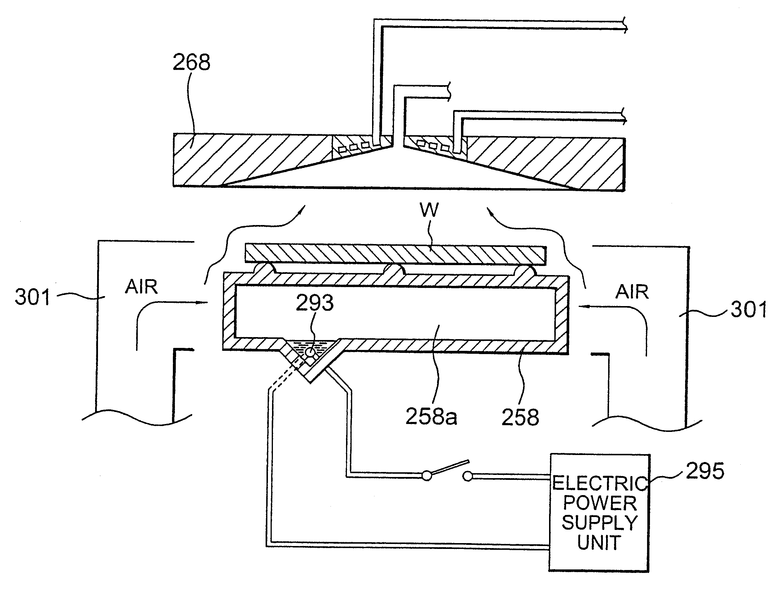
FIG. 13 is a vertical cross section of a cover assembly 268 involving one embodiment corresponding to the second invention, and FIG. 14 is a plan view showing a state seen from the bottom side of the cover assembly 268. As shown in FIG. 13, on the lower surface side of the cover assembly 268, a conical concave portion 168b is formed, and at the summit of the cone, an exhaust outlet 268a is disposed, and a lower end of an exhausting pipe 270 is connected to this exhaust outlet 268a. The other end side of the exhausting pipe 270 is connected to a not shown exhausting system, the heating gas (nitrogen gas) which is heated by the thermal surface plate and went up is collected by the conical concave portion 268b, and evacuated through the exhaust outlet 268a and exhausting pipe 270.

On the central portion of the conical concave 268b, a through hole 268c is disposed, and to this through hole 268c, a jacket for cooling a gas (hereinafter refers simply as "jacket") 290 is attached.

This jacke...


PUM

PropertyMeasurementUnit
temperatureaaaaaaaaaa
temperaturesaaaaaaaaaa
specific gravityaaaaaaaaaa

Abstract

A heat treatment table is divided into two or more regions, a heater is disposed for each region. On a predetermined portion of the heat treatment table, a plurality of sensors are disposed separately each other. A relation between temperatures of the respective portions on the heat treatment table and temperatures detected by the sensors is grasped in advance, thereby enables to surmise a temperature of the respective portion of the heat treatment table from the temperature detected by the sensors. In the case of an wafer being actually treated by placing on the heat treatment table, the temperatures detected by the sensors are observed, from these detected temperatures, the temperatures of the respective portions on the heat treatment table, that is, temperatures affecting the wafer, are surmised.

Description

1. Field of the InventionThe present invention relates to a heat treatment apparatus such as a heater or a pre-heater to be assembled in a semiconductor manufacturing system for manufacturing semiconductor elements by use of a photomechanical process, for instance.2. Description of the Related ArtConventionally, in a semiconductor manufacturing system which employs a photomechanical process, various kinds of treatment units such as a resist coating unit, a drying unit, a heating unit and the like are assembled in one system. And, a string of treatments are carried out while transferring among these various kinds of treatment units in turn.FIG. 12 shows a vertical cross section of a typical heat treatment unit 500.In this heat treatment unit 500, a semiconductor wafer (hereinafter simply refers to as "wafers") W is disposed on an upper surface of a heat treatment table 501, and the wafer W is heated by heat evolved from the heat treatment table 501. In this heat treatment table 501, ...

Claims


Application Information

Patent Timeline
Patent Type & Authority Patents(United States)
IPC IPC(8): H01L21/00H01L21/324
CPCH01L21/67109H01L21/67248A01B49/06A01C5/062A01C23/021
Inventor SHIRAKAWA, EIICHISATA, NOBUYUKI
Owner TOKYO ELECTRON LTD
Why Eureka
Try Eureka