
Adaptive sensor array apparatus

a sensor array and array technology, applied in the direction of amplitude demodulation, line-fault/interference reduction, pulse technique, etc., can solve the problems of poor interference cancellation, computational complexity, and arrays not always stationary with respect, and achieve the effect of improving the rejection of output signals

Inactive Publication Date: 2002-09-17
QINETIQ LTD
View PDF9 Cites 18 Cited by
  • Summary
  • Abstract
  • Description
  • Claims
  • Application Information

AI Technical Summary

Benefits of technology

to provide an alternative adaptive sensor array apparatus providing enhanced interference rejection characteristics.
thereby providing enhanced rejection in the output signal of contributions arising from interfering radiation received at the elements (22).

Problems solved by technology

As a result, the arrays are not always stationary with respect to wanted targets and unwanted sources of jamming and interfering radiation within fields of view of the apparatus.
However, as disclosed in a publication "A Kalman-type algorithm for adaptive radar arrays and modelling of non-stationary weights" IEE Conference Publication, 180, 1979 by J E Hudson, the assumption may be invalid for apparatus incorporating adaptive sensor arrays operating on future agile platforms which will be capable of performing more rapid trajectory changes in comparison to current platforms.
Although the solution can provide improved tracking of more rapidly changing scenes, it suffers a problem of providing poor cancellation of interference when there are multiple interference sources within a field of view of the apparatus.
Moreover, the solution is more computationally complex than conventional solutions for adaptive beam forming.
These alternative solutions have a disadvantage that a polar gain response of an apparatus provided thereby becomes unacceptably distorted when sources of jamming are located in a direction of a mainbeam response provided by the apparatus, or where there are multiple jamming and interference sources located in directions away from the direction of the mainbeam response where a residual polar gain sidelobe response is provided by the apparatus.

Method used


Image

  • Adaptive sensor array apparatus
  • Adaptive sensor array apparatus
  • Adaptive sensor array apparatus

Examples


Embodiment Construction

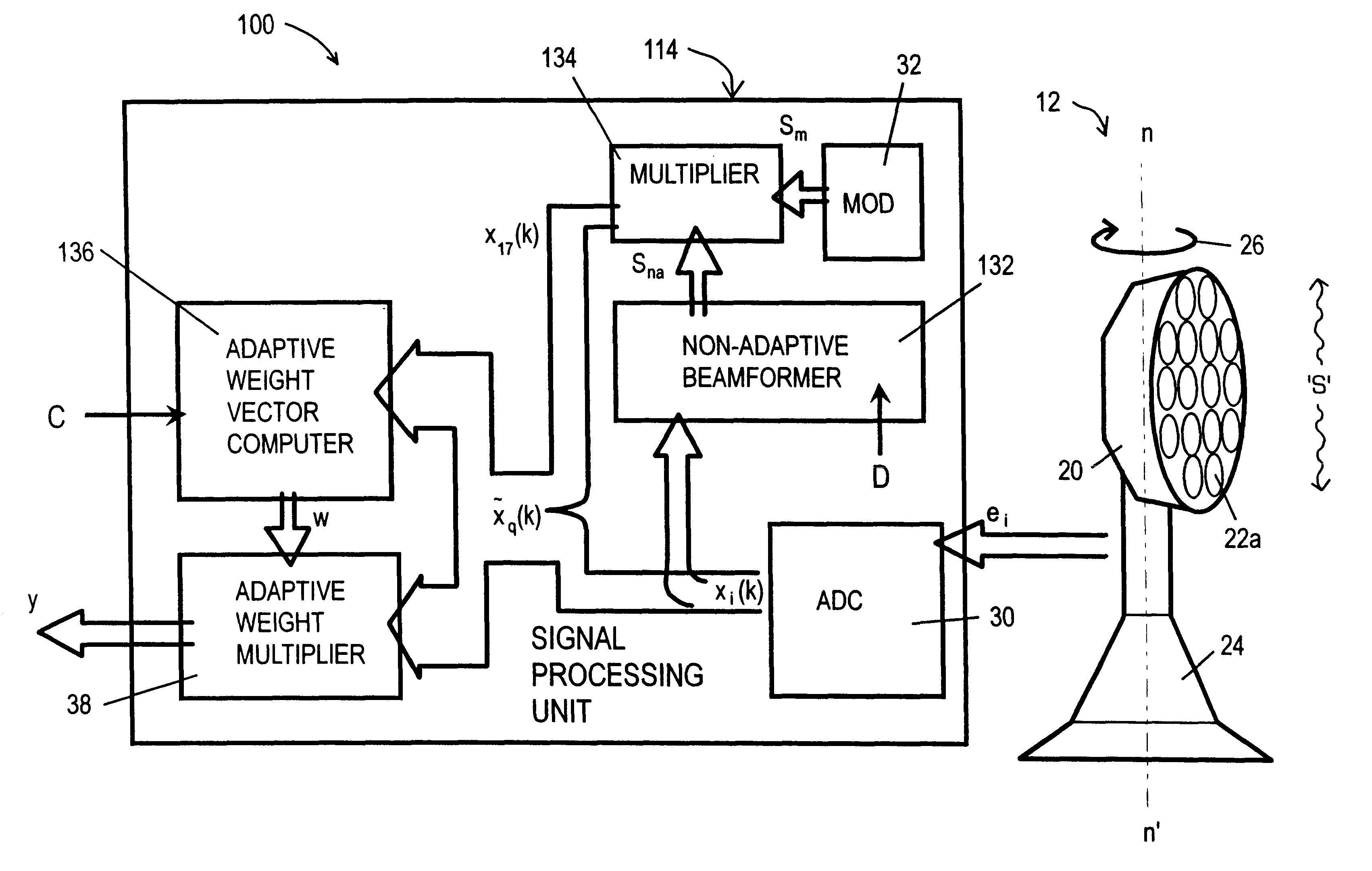
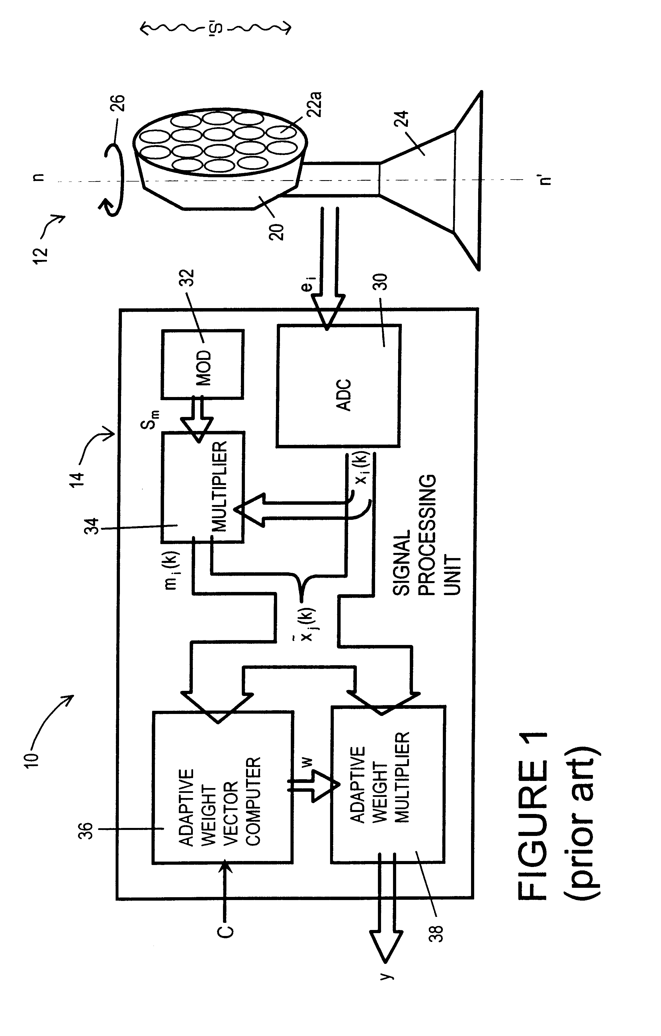
Referring to FIG. 1, a prior art adaptive sensor array apparatus is indicated generally by 10. The apparatus 10 comprises a multielement antenna indicated by 12 and a processing unit indicated by 14. The antenna 12 incorporates an array 20 of sixteen microwave antenna sensor elements 22 such as an element 22a. The array 20 is rotatably mounted onto a mount 24 so that the elements 22 are orientatable through 360.degree. about an axis n-n' to receive radiation in various directions from different parts of a scene, represented by `S`, surrounding the antenna 12. Each element 22 is arranged to provide an analogue sensor output signal e.sub.i at an output which is connected to the unit 14 for processing; i is a reference index in a range of one to sixteen for identifying each element 22 uniquely.

The unit 14 incorporates an analogue-to-digital (ADC) converter unit 30, a modulation unit (MOD) 32, a multiplier unit (MULTIPLIER) 34, an adaptive weight vector computer 36 and an adaptive weigh...


PUM


Abstract

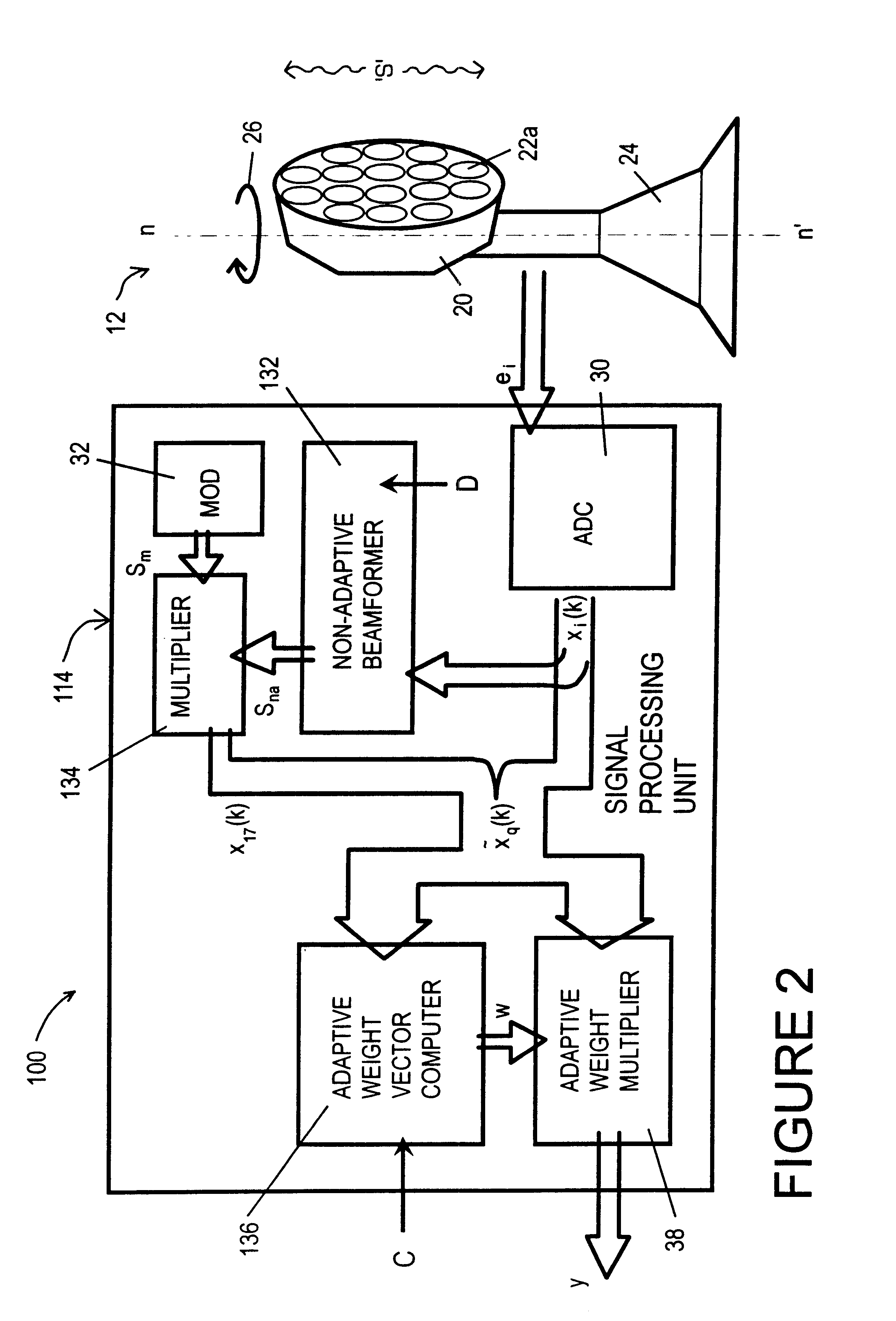
The invention provides an adaptive sensor array apparatus (100) incorporating a multielement antenna (12) for receiving radiation from a scene ("S') and generating signals (e) in response thereto and a processing unit (114) for processing the signals (e) to provide an output signal (y). The unit (114) comprises an adaptive weight computer (136) arranged to generate weighting vectors (w) which are used in the unit (114) to attenuate contributions to the output signal (y) arising from sources of jamming radiation in the scene and transmit contributions to the output signal (y) arising from wanted targets therein. The apparatus (100) incorporates a non-adaptive beamformer unit (132) for preconditioning the signals (e) before they are passed to the computer (136). Preconditioning the signals (e) enhances performance of the apparatus (100) relative to conventional adaptive sensor array apparatus (10).

Description

1. Field of the InventionThis invention relates to an adaptive sensor array apparatus and a method of obtaining interference rejection.2. Discussion of Prior ArtArrays of sensors connected to associated signal processing units are well known. The sensors generate signals in response to received radiation for subsequent processing in the units to provide output signals. Each sensor signal is scaled and phase shifted by an associated weighting vector w in a processing unit to provide a corresponding conditioned signal. Conditioned signals from the sensors are summed in the unit to provide a processed output signal therefrom in a process known as beamforming. By phase shifting and amplitude scaling each of the signals in a controlled manner prior to combining them, the processing unit exhibits in its output signal a polar gain response to received radiation comprising one or more directions of enhanced gain and one or more directions of attenuation; the directions of enhanced gain are ...

Claims


Application Information

Patent Timeline
IPC IPC(8): H01Q3/26
CPCH01Q3/2605
Inventor HAYWARD, STEPHEN D.
Owner QINETIQ LTD
Learn More