Cooling arrangement for an electrical machine of a vehicle

a technology of electrical machines and cooling arrangements, which is applied in the direction of mechanical equipment, mechanical energy handling, machines/engines, etc., can solve the problems of power loss of the machine, heat loss, copper loss and iron loss,

Inactive Publication Date: 2002-09-24
ZF FRIEDRICHSHAFEN AG
View PDF17 Cites 19 Cited by
  • Summary
  • Abstract
  • Description
  • Claims
  • Application Information

AI Technical Summary

Problems solved by technology

Among other things, a heat loss, which as a rule results from copper losses and iron losses, is produced during the operation of such electrical machines.
However, the heat loss in the electrical machine is undesirable, since it may lead to power losses of the machine and to damage of the latter in the worst case.
However, the known solutions have a number of disadvantages.
Thus cooling of the electrical machine is only possible at a high design cost.
The known cooling arrangements are therefore also relatively costly.
In vehicles with a limited amount of space available in the engine compartment, the known cooling arrangements are particularly disadvantageous in that an excessive amount of the installation space, which is limited anyway, is taken up by a multiplicity of requisite secondary units.
Finally, some of the secondary units, such as pumps for example, in turn consume electrical energy, a factor which has an adverse effect on the energy balance of the electrical machine.

Method used


Image

  • Cooling arrangement for an electrical machine of a vehicle
  • Cooling arrangement for an electrical machine of a vehicle
  • Cooling arrangement for an electrical machine of a vehicle

Examples


Embodiment Construction

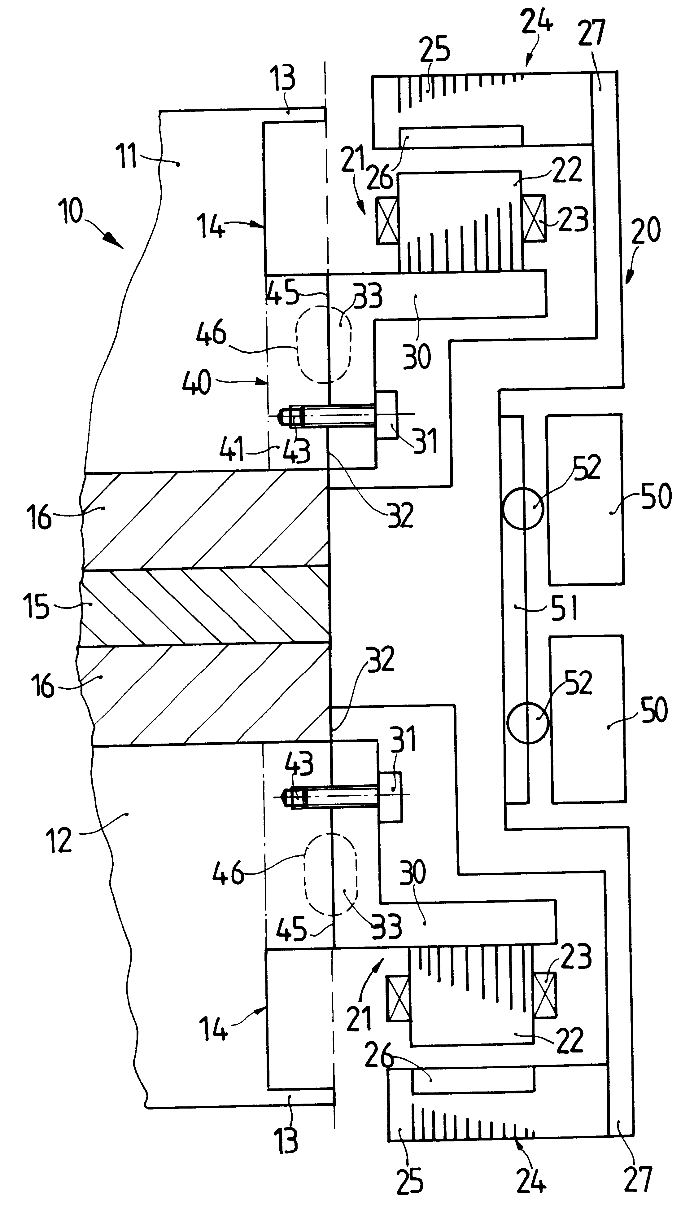
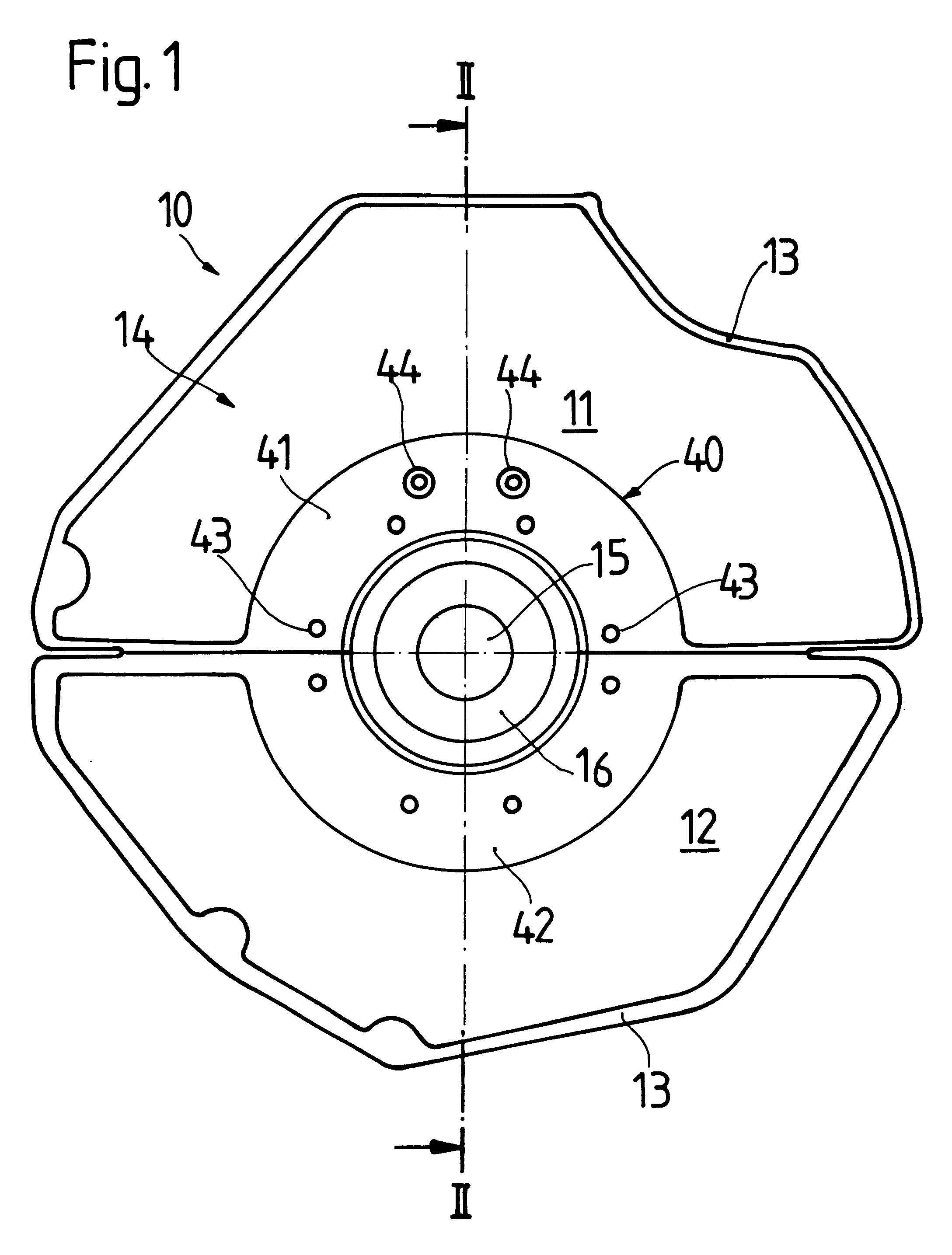
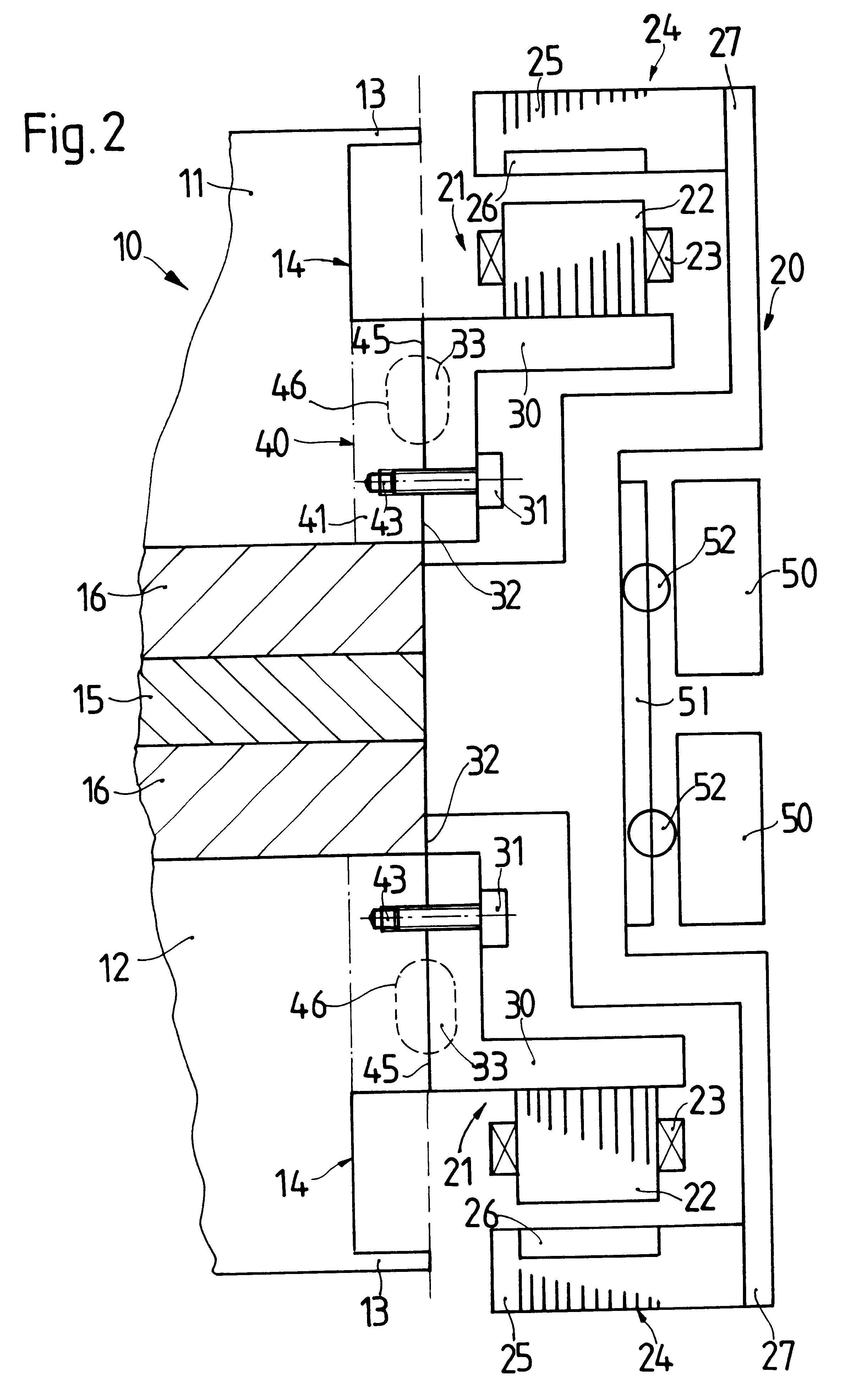
FIG. 1 shows an engine block 10, which is made of cast material and consists of two engine-block halves 11 and 12. Each of the engine-block halves 11 and 12 has a number of webs 13 which are conventional in engine building. The two engine-block halves 11 and 12 surround a crankshaft 15, which is supported and sealed via a crankshaft bearing 16.

The engine block 10 has a cooling element 40, which is formed from two half-ring-shaped cooling-element segments 41 and 42. The cooling-element segments 41 and 42 form an essentially annular cooling element 40, which is arranged concentrically around the crankshaft 15 of the engine block 10. The individual cooling-element segments 41 and 42 are formed integrally with the engine-block halves 11, 12. This means that the cooling-element segments 41, 42 are produced at the same time along with the engine-block halves 11, 12 during the casting process. The height of the cooling element 40 corresponds approximately to the height of the webs 13.

For t...


PUM


Abstract

A cooling arrangement for an electrical machine-for example, a permanent-field synchronous machine of a vehicle. The electrical machine is connected to the engine block of the vehicle. In order to ensure cost-effective cooling of the electrical machine, the electrical machine includes a support element, and the engine block includes a cooling element. At least a region of the electrical machine is connected via the support element to the cooling element of the engine block such that the heat generated during operation of the electrical machine dissipates thermally into the engine block.

Description

1. Field of the InventionThe present invention relates to motor vehicles, and more particularly to a cooling arrangement for an electrical machine of a vehicle, the electrical machine being connected to the engine block of the vehicle.2. Description of the Related ArtSuch electrical machines are, for example, synchronous machines for generating electrical energy. The generated electrical energy is then made available to all kinds of devices in the vehicle. Among other things, a heat loss, which as a rule results from copper losses and iron losses, is produced during the operation of such electrical machines. However, the heat loss in the electrical machine is undesirable, since it may lead to power losses of the machine and to damage of the latter in the worst case.The electrical machine must therefore be cooled in order to reduce the heat loss produced in it. To this end, cooling arrangements independent of the electrical machine have been used heretofore. Such cooling arrangements...

Claims


Application Information

Patent Timeline
Patent Type & Authority Patents(United States)
IPC IPC(8): F01P3/20H02K9/22H02K7/00H02K9/19F01P3/12H02K7/18
CPCF01P3/20H02K7/006H02K9/19H02K9/22F01P2060/185H02K9/227H02K9/223
Inventor DEMONT, STEFANWEIMER, JURGENBAUCH-PANETZKY, DIETER
Owner ZF FRIEDRICHSHAFEN AG
Why Eureka
Try Eureka