Amplitude change time activated phase locked controller in a selective call receiver

a phase lock controller and amplitude change technology, applied in the field of radio selective call receivers, can solve problems such as reducing the accuracy of phase control

Inactive Publication Date: 2002-09-24
NEC CORP
View PDF18 Cites 28 Cited by
  • Summary
  • Abstract
  • Description
  • Claims
  • Application Information

AI Technical Summary

Problems solved by technology

In systems using an M-ary (M>2) FSK method such as 4-ary FSK method, however, there occurs a problem t

Method used


Image

  • Amplitude change time activated phase locked controller in a selective call receiver
  • Amplitude change time activated phase locked controller in a selective call receiver
  • Amplitude change time activated phase locked controller in a selective call receiver

Examples


Embodiment Construction

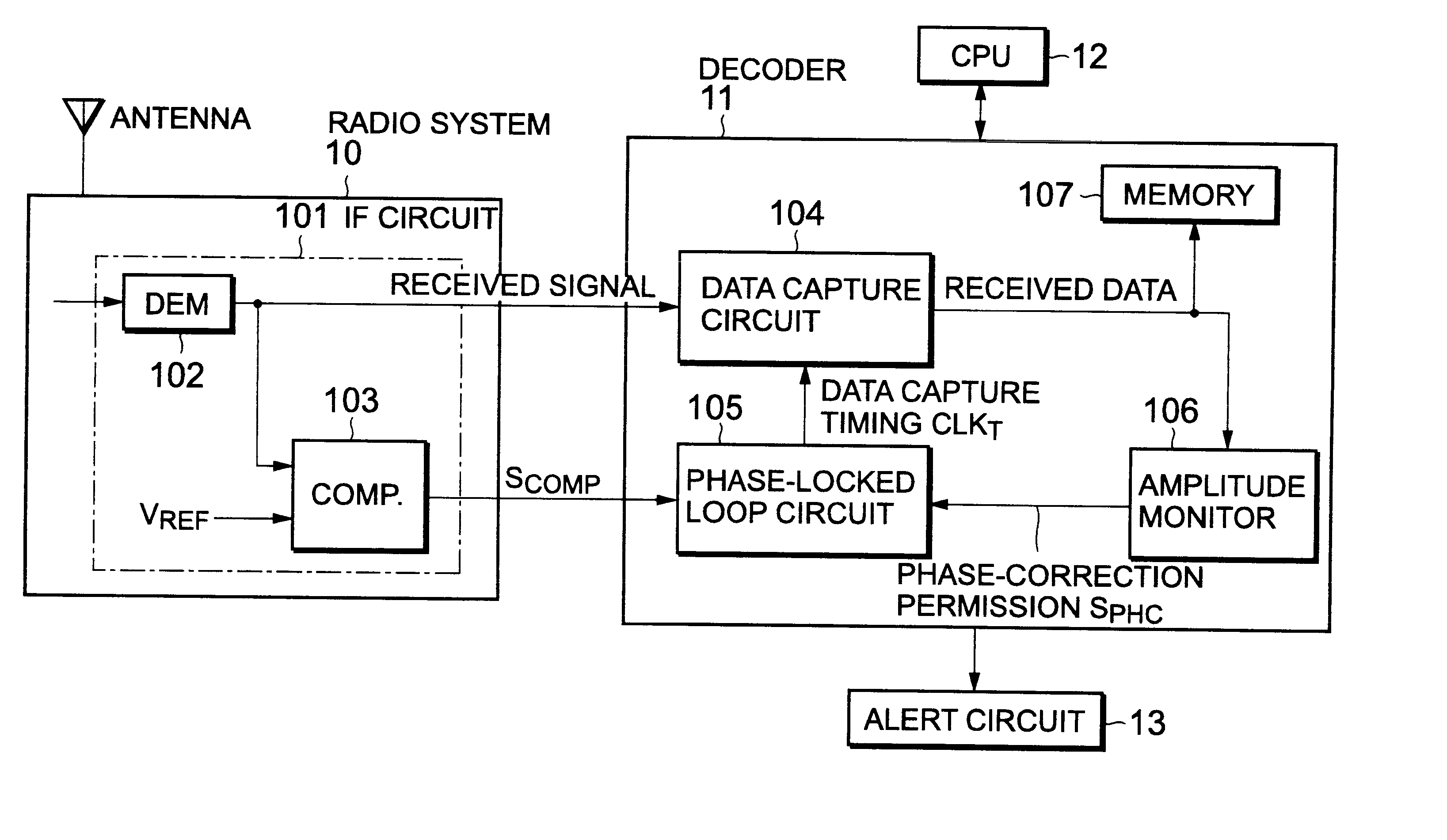
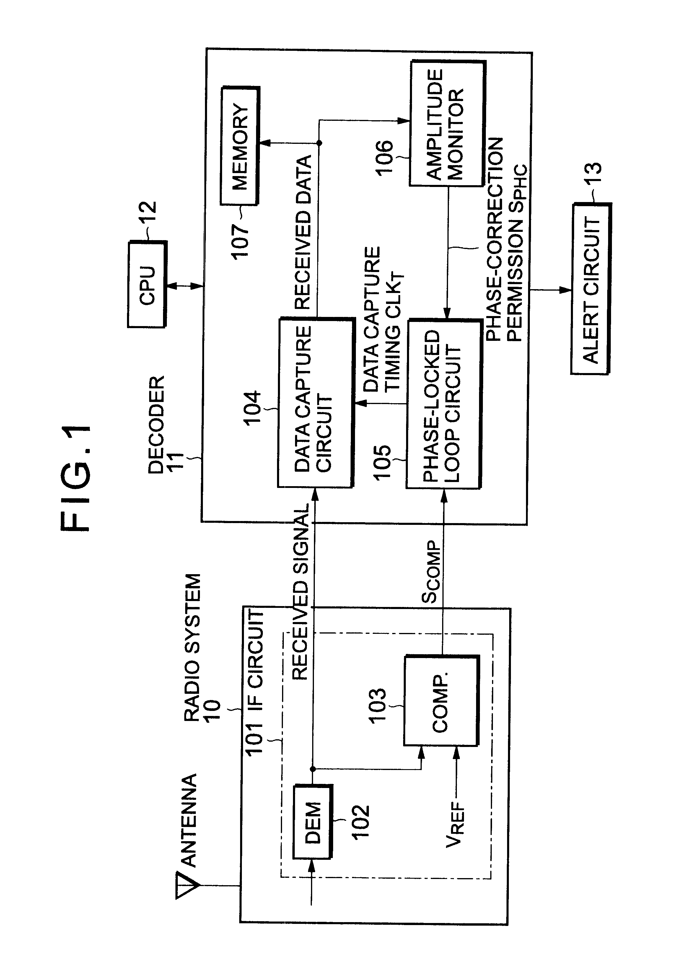
With reference to FIG. 5, a radio selective call receiver according to another embodiment has the same configuration as that as shown in FIG. 1, excepting that a first comparator 501, a second comparator 502, and a third comparator 503 are provided in the IF circuit 101. The similar circuit blocks are denoted by the same reference numerals.

The first comparator 501 is provided with a middle voltage in level between "01" and "10" as its reference voltage V.sub.REF1. The second comparator 502 is provided with a middle voltage in level between "00" and "10" as its reference voltage V.sub.REF2. The third comparator 503 is provided with a middle voltage in level between "00" and "11" as its reference voltage V.sub.REF3. Therefore, the first comparator 501 compares the output of the demodulator 102 with its reference voltage V.sub.REF1 to output a resultant comparison signal S.sub.COMP1. The second comparator 502 compares the output of the demodulator 102 with its reference voltage V.sub.R...


PUM


Abstract

A radio receiver with improved accuracy of phase-locked loop is disclosed. In addition to a detector for detecting a detected signal from a received radio signal, the receiver includes a monitor for monitoring an amplitude change of the detected signal to detect timing where the amplitude change occurs over a predetermined range. The phase-locked control of the timing clock signal with respect to the detected signal is performed only when the timing is detected by the monitor.

Description

1. Field of the InventionThe present invention relates to a radio selective call receiver, and in particular to a phase-locked loop control method for the radio selective call receivers2. Description of the Related ArtIn conventional radio selective call receivers, the phase-locked loop control is performed for all change points using the output of a comparator having only one reference value.For example, in a technique disclosed in Japanese Patent Laid-open No. 7-154434, an average value of a detected signal at the time of detection of a preamble signal is derived, and the code decision of the detected signal is made by using the average value of the detected signal as a reference level by means of digital signal processing.Even if a variation is caused in the middle voltage of the detected signal due to a variation of the transmission frequency, a temperature change of the receiver, a supply voltage variation, and the like, errors of the code decision are reduced by the above desc...

Claims


Application Information

Patent Timeline
IPC IPC(8): H03L7/08H03L7/085H04L7/033H04B1/10H04Q7/14H04L27/14H04L7/00H04W56/00H04W88/02
CPCH03L7/085H04B1/1027H04L7/033
Inventor TADA, KEN-ICHI
Owner NEC CORP
Why Eureka
Try Eureka