
Multifuel internal combustion stirling engine

Inactive Publication Date: 2002-10-01
FIREY JOSEPH CARL
View PDF5 Cites 37 Cited by
  • Summary
  • Abstract
  • Description
  • Claims
  • Application Information

AI Technical Summary

Benefits of technology

To obtain adequate fuel efficiency from prior art external combustion, Stirling cycle engines requires the use of expensive superalloy materials for the heat exchangers, where the working fluid is heated. A principal beneficial object of the multifuel internal combustion Stirling engine of this invention is that internal combustion is used instead of a heat exchanger and these expensive superalloy heat exchangers are avoided.
When coal or other solid fuels are burned in conventional prior art internal combustion engines, the resulting abrasive ash particles cause severe engine wear and consequently increased engine maintenance costs. In a multifuel internal combustion Stirling engine of this invention, the burned gases containing the abrasive ash particles are retained within the burned gas volume and do not contact that portion of the cylinder over which the compressor piston moves. In this way ash particle wear of the engine is largely avoided, since the displacer piston is not pressure loaded and does not require use of gas tight seals, such as piston rings. This is another beneficial object of the multifuel internal combustion Stirling engines of this invention, that coal fuels and coal water slurry fuels can be used without excessive engine wear.

Problems solved by technology

Our national dependence on imported petroleum aggravates our trade imbalance and creates a wartime vulnerability to blockade.
But the resulting ash particles caused increased wear of engine cylinders and piston rings.
Aggravated wear also occurred on the fuel injector nozzles.
As a result, this development work has been discontinued.
(1) "Stirling Engines," G. T. Reader and C. Hooper, E. & F. N. Spon, New York, 1983.
(2) "Stirling Engines," G. Walker, Clarendon Press, Oxford, 1980; To achieve competitive fuel efficiency, and engine size, required the use of expensive superalloy materials, for the heat exchangers, and special seals, to contain the working fluids at very high pressures. As a result, these recently developed Stirling Cycle engines have failed to replace conventional internal combustion engines.
These prior art internal combustion Stirling engines utilized fuels which did not create abrasive wear particles, and were not capable of durable operation on ash producing fuels, such as coal.
The greater mechanical complexity of the Stirling engine mechanism, as compared to conventional internal combustion engines, prevented these prior art internal combustion Stirling engines from successfully competing against conventional internal combustion engines.

Method used


Image

  • Multifuel internal combustion stirling engine
  • Multifuel internal combustion stirling engine
  • Multifuel internal combustion stirling engine

Examples


Embodiment Construction

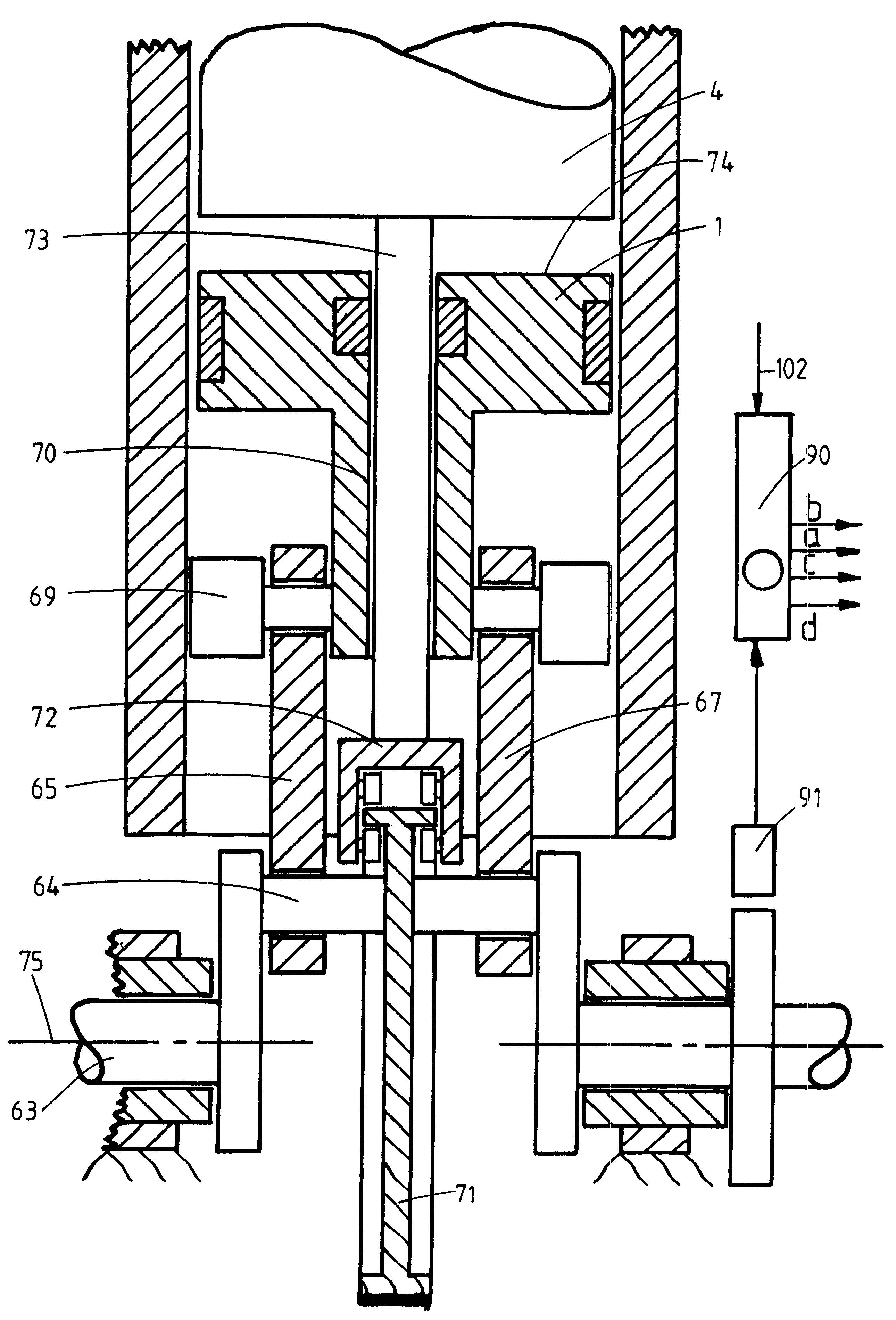
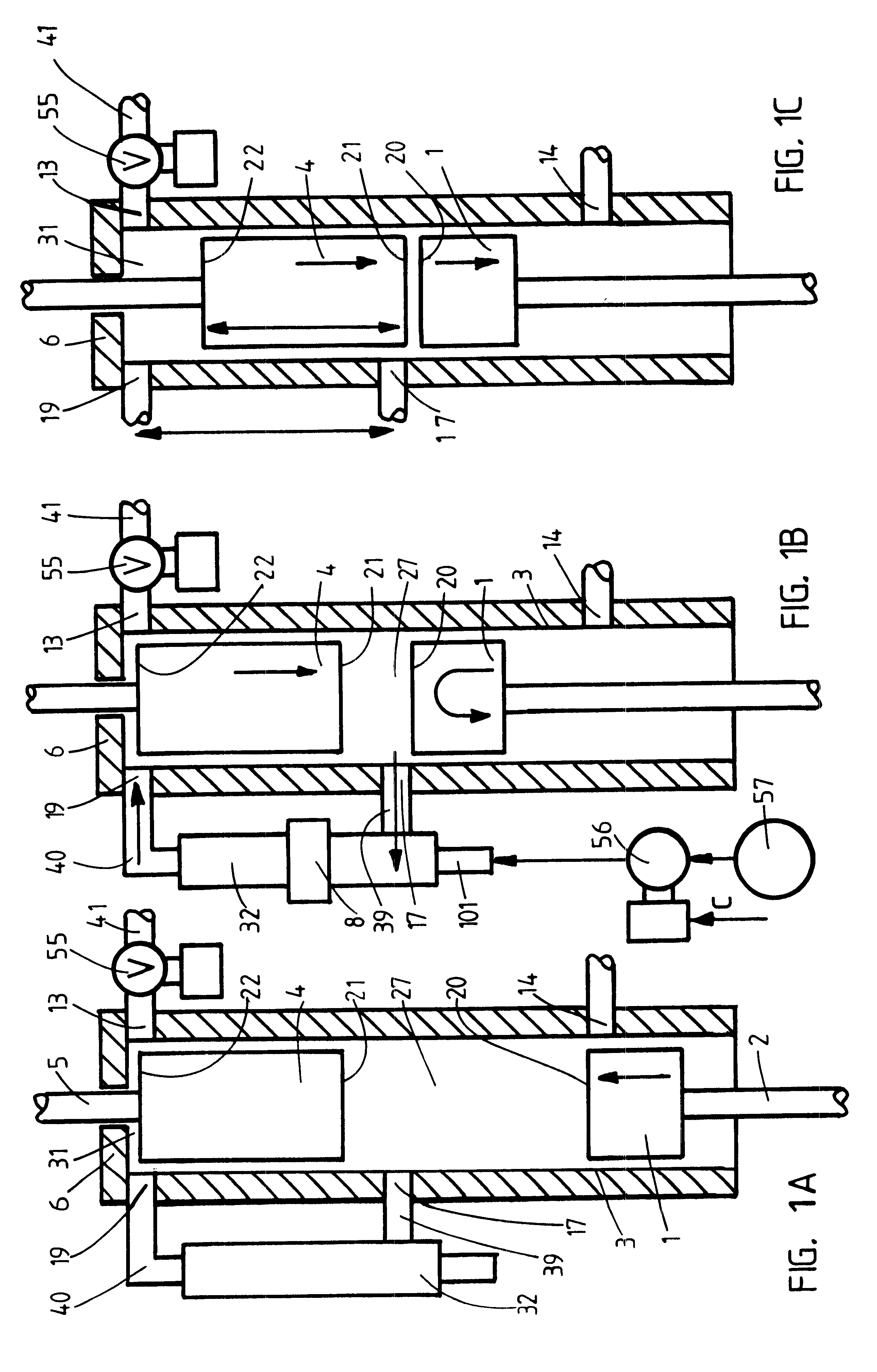
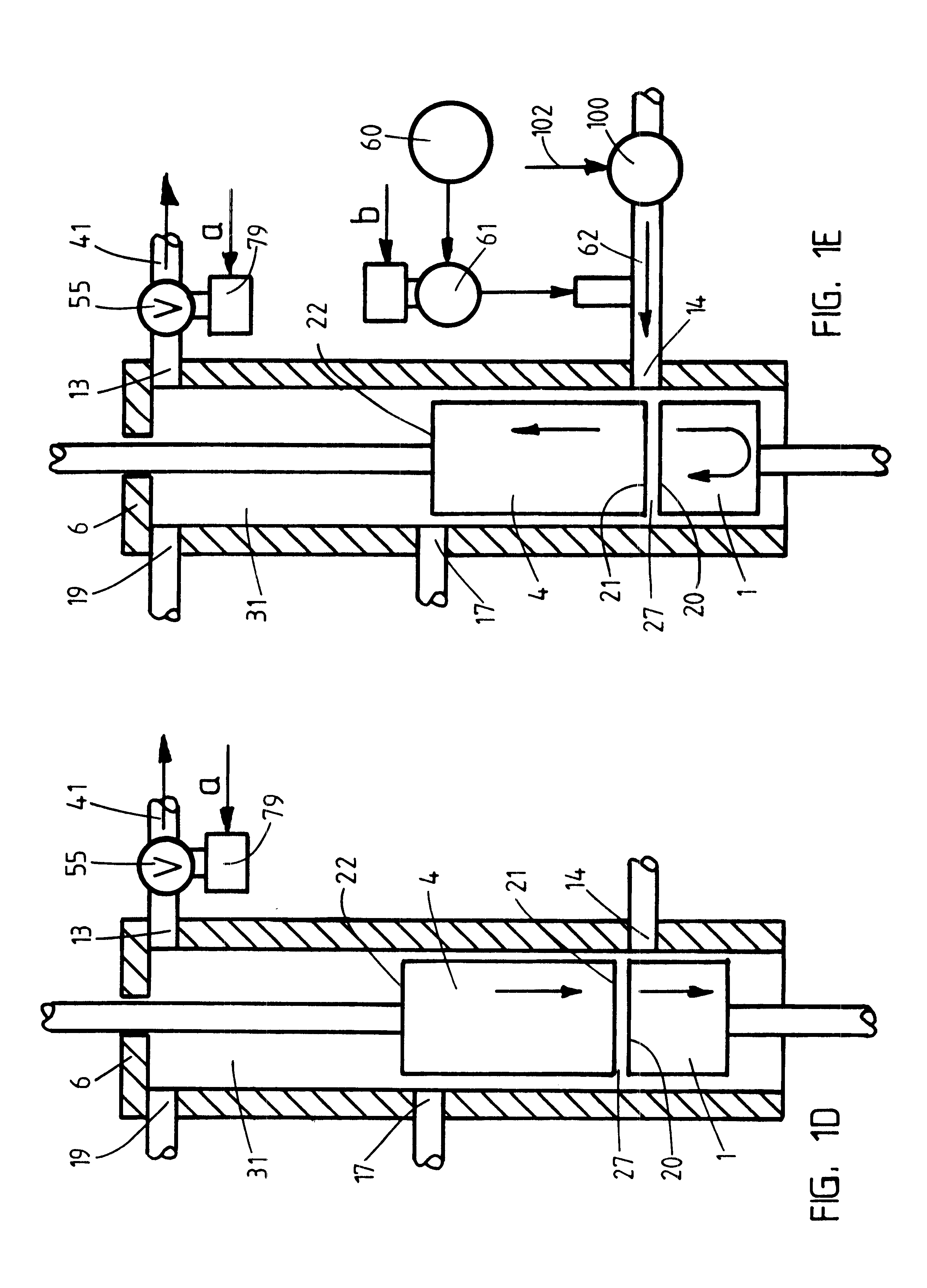
A. Multifuel Internal Combustion Stirling Engines Cycle The cycle of operation, by a multifuel internal combustion Stirling engine of this invention, utilizes a compressor piston and a displacer piston, both driven to reciprocate within the same engine cylinder as shown schematically in FIGS. 1A, 1B, 1C, 1D, and 1E:

1. The compressor piston, 1, is driven via its piston rod, 2, back and forth through a fixed compressor piston stroke length, within the engine cylinder, 3;

2. The displacer piston, 4, is driven via its piston rod, 5, back and forth, within the engine cylinder, 3;

3. The engine cylinder, 3, comprises a gas cylinder head, 6, at the displacer piston end thereof, an exhaust port, 13, an intake air port, 14, an air transfer port, 17, and a burned gas port, 19;

4. The compressor piston comprises an air crown, 20, on the displacer piston side thereof; the displacer piston comprises an air crown, 21, on the compressor piston side thereof, and a gas crown, 22, on the gas cylinder he...


PUM


Abstract

A multifuel internal combustion Stirling engine is described, wherein a compressor piston and a displacer piston reciprocate, within a common cylinder, to enclose a variable air volume, and a variable burned gas volume. Motion of these two pistons, creates a power producing cycle, of compression, combustion, expansion, and scavenge, wherein the burned gases do not contact those cylinder portions over which the compressor piston moves. In this way low engine wear can be obtained when using fuels such as coal, which produces abrasive particulates in the burned gases. A multifuel internal combustion engine of this invention can be readily adapted to operate on a wide variety of fuels, such as, natural gas, diesel fuel, residual petroleum fuel, and coal. Widespread use of these engines would introduce economic competition between these now separately competing fuels. This is a clear route to national energy independence, since coal reserves greatly exceed petroleum reserves, nationally and internationally.

Description

(B) BACKGROUND OF THE INVENTION1. Field of the InventionThis invention is principally in the field of internal combustion engines, and particularly internal combustion engines for burning solid fuels, such as coal or coke, as well as liquid and gas fuels. This invention is also related to the field of external combustion, Stirling cycle, engines.2. Description of the Prior ArtOur national dependence on imported petroleum aggravates our trade imbalance and creates a wartime vulnerability to blockade. Greater use of domestic coal, particularly in transportation engines, could reduce both the vulnerability and the trade imbalance. Domestic coal reserves, as well as worldwide coal reserves, are much larger than petroleum or natural gas reserves. Additionally, coal is much less costly, per unit of energy, than natural gas or petroleum derived fuels. It has thus been recognized for some time that it would be very much in the national interest to have available an efficient and durable tra...

Claims


Application Information

Patent Timeline
IPC IPC(8): F02G1/00F02G1/043
CPCF02G1/043F02G2243/02F02G2258/50F02G2270/45
Inventor FIREY, JOSEPH CARL
Owner FIREY JOSEPH CARL
Learn More