Method and system for enhanced engine control based on exhaust temperature

a technology of engine control and exhaust temperature, applied in the direction of electric control, machines/engines, mechanical equipment, etc., can solve the problems of ineffective engine efficiency, inability to effectively control engine temperature and associated component temperature, and electronic control unit not being configured to be used in hazardous or potentially hazardous environments, etc., to achieve the effect of improving engine efficiency

Inactive Publication Date: 2002-10-01
MTU DETROIT DIESEL
View PDF16 Cites 26 Cited by
  • Summary
  • Abstract
  • Description
  • Claims
  • Application Information

AI Technical Summary

Benefits of technology

The invention addresses the shortcomings of the prior art by providing an improved method and system for controlling engine operation, wherein the method and system are especially useful in hazardous or potentially hazardous environments. The method and system of the invention provide significantly improved engine efficiency compared with prior art systems and methods that include mechanically controlled engines.
Advantageously, operating temperatures of the system may be effectively controlled by the method of the invention so as to allow the system to operate in hazardous and potentially hazardous environments. Furthermore, the method allows the engine to continue operation when the temperature threshold is exceeded. Thus, an operator is provided time to respond to a situation, rather than having the engine abruptly shut down.
Adjusting an engine control parameter preferably includes reducing available engine torque. As a result, fuel supplied to the engine is reduced, but the engine may continue to operate. Other examples of adjusting an engine control parameter include adjusting timing of a fuel injection to the engine, adjusting air supplied to the engine, adjusting exhaust gas re-circulation rate, and reducing engine loading.

Problems solved by technology

Furthermore, fuel injection timing for such engines is a function of engine load, and not engine speed.
As a result, these engines are inefficient.
Such an electronic control unit, however, is not configured to be used in hazardous or potentially hazardous environments, and does not include a means for effectively controlling engine temperatures and associated component temperatures.

Method used


Image

  • Method and system for enhanced engine control based on exhaust temperature
  • Method and system for enhanced engine control based on exhaust temperature
  • Method and system for enhanced engine control based on exhaust temperature

Examples


Embodiment Construction

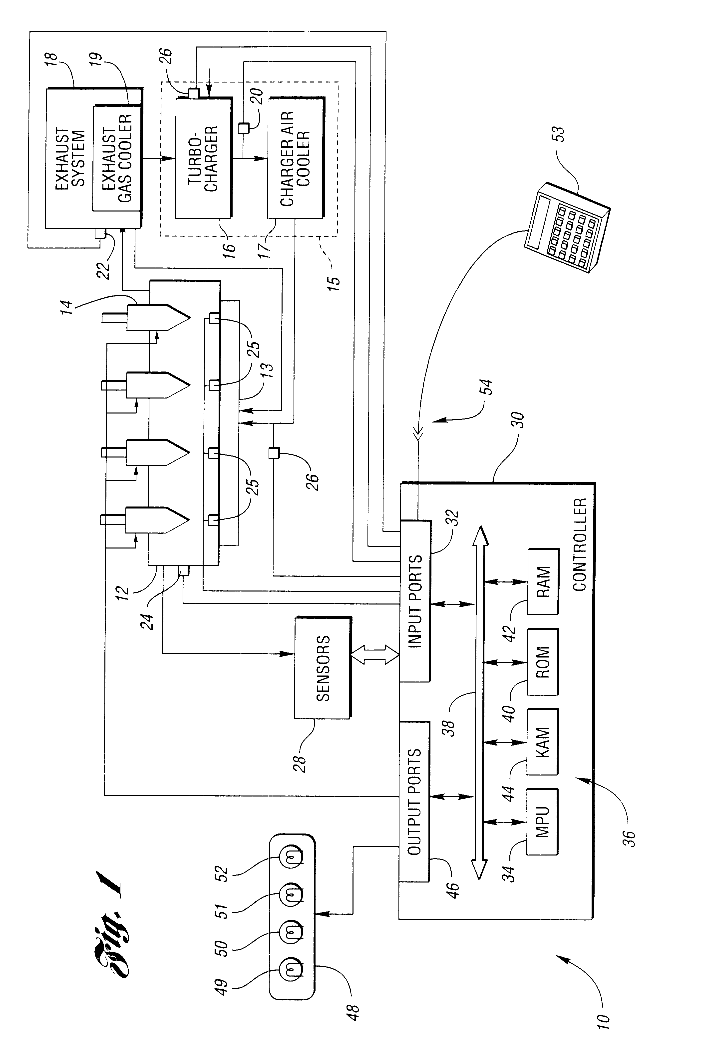
FIG. 1 shows a system for controlling engine operation. While the system may be used in any suitable environment, the system is particularly useful in a hazardous or potentially hazardous environment, as explained below in greater detail. Hazardous or potentially hazardous environments include environments in which combustible materials are present in either a confined or unconfined state. Such environments may include, for example, underground mining operations, construction operations and offshore drilling operations. The system may be used with a vehicle or any other engine-operated equipment such as mining equipment, construction equipment and / or drilling / pumping equipment. Examples of such equipment include mud pumps and fracturing units.

The system, generally indicated by reference numeral 10, includes an engine 12 having an air inlet manifold 13 and a plurality of cylinders, each of which is fed by one or more fuel injectors 14. In a preferred embodiment, engine 12 is a multi-...


PUM


Abstract

A method is provided for controlling an engine of a system having an exhaust system connected to the engine, and the exhaust system includes an exhaust gas cooler. The method includes sensing exhaust system temperature downstream of the exhaust gas cooler; comparing the exhaust system temperature to a temperature threshold that is less than 200 degrees Celsius; and adjusting an engine control parameter when the exhaust system temperature exceeds the temperature threshold. A system for controlling engine operation is also provided.

Description

The invention relates to a method and system for controlling operation of a system based on exhaust system temperature measured downstream of an exhaust gas cooler.Some internal combustion engines are designed to be used in hazardous or potentially hazardous environments, such as underground mining applications and offshore drilling applications. Typically, such engines are mechanically controlled. More specifically, fuel injections are controlled based on movement of a cam shaft. Furthermore, fuel injection timing for such engines is a function of engine load, and not engine speed. As a result, these engines are inefficient.For non-hazardous environments, engines are typically controlled by an electronic control unit having volatile and non-volatile memory, input and output driver circuitry, and a processor capable of executing a stored instruction set. A particular electronic control unit communicates with numerous sensors, actuators, and other control units to control various fun...

Claims


Application Information

Patent Timeline
Patent Type & Authority Patents(United States)
IPC IPC(8): F01N3/02F02D41/14F02B39/16F02B39/00
CPCF01N3/02F02B39/16F02D41/1446F01N2240/02F02D41/0055F02D2041/0067F02D2250/18Y02T10/20Y02T10/12
Inventor RITTER, CURTIS P.HAWKINS, JEFFERY S.MCKENZIE, IAN D.
Owner MTU DETROIT DIESEL
Why Eureka
Try Eureka