
Lighting system with a high-pressure discharge lamp

a discharge lamp and lighting system technology, applied in the field of lighting systems, can solve problems such as inability to continue to us

Inactive Publication Date: 2002-10-08
OSRAM SYLVANIA INC
View PDF9 Cites 34 Cited by
  • Summary
  • Abstract
  • Description
  • Claims
  • Application Information

AI Technical Summary

Benefits of technology

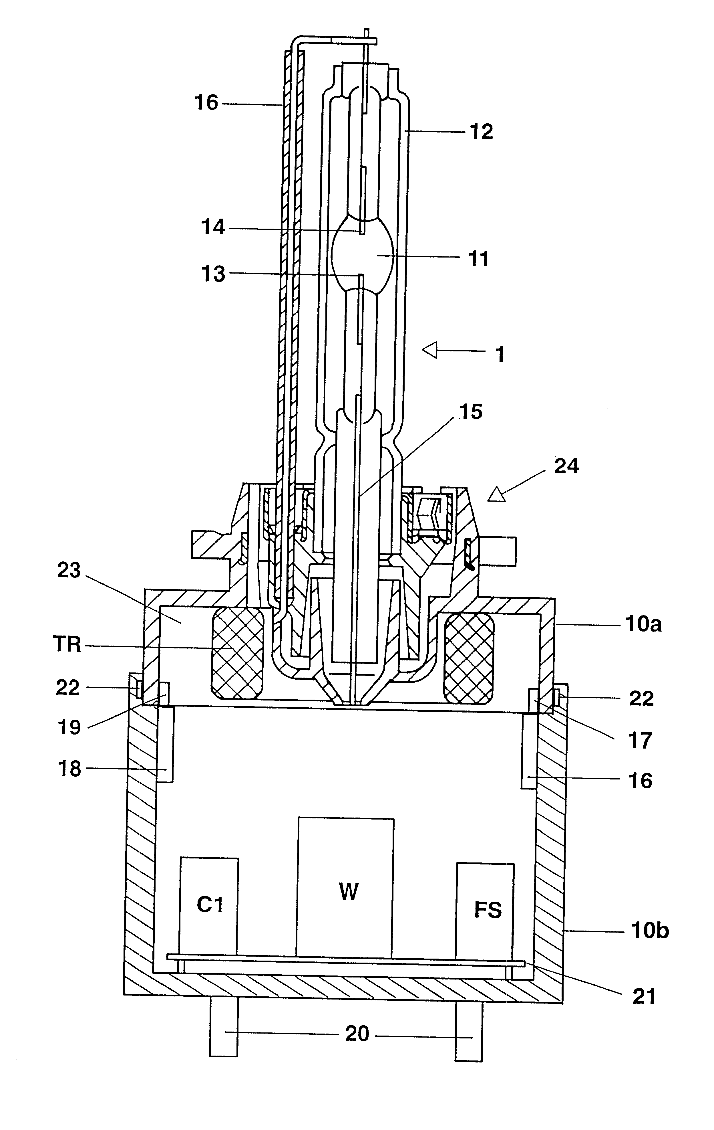
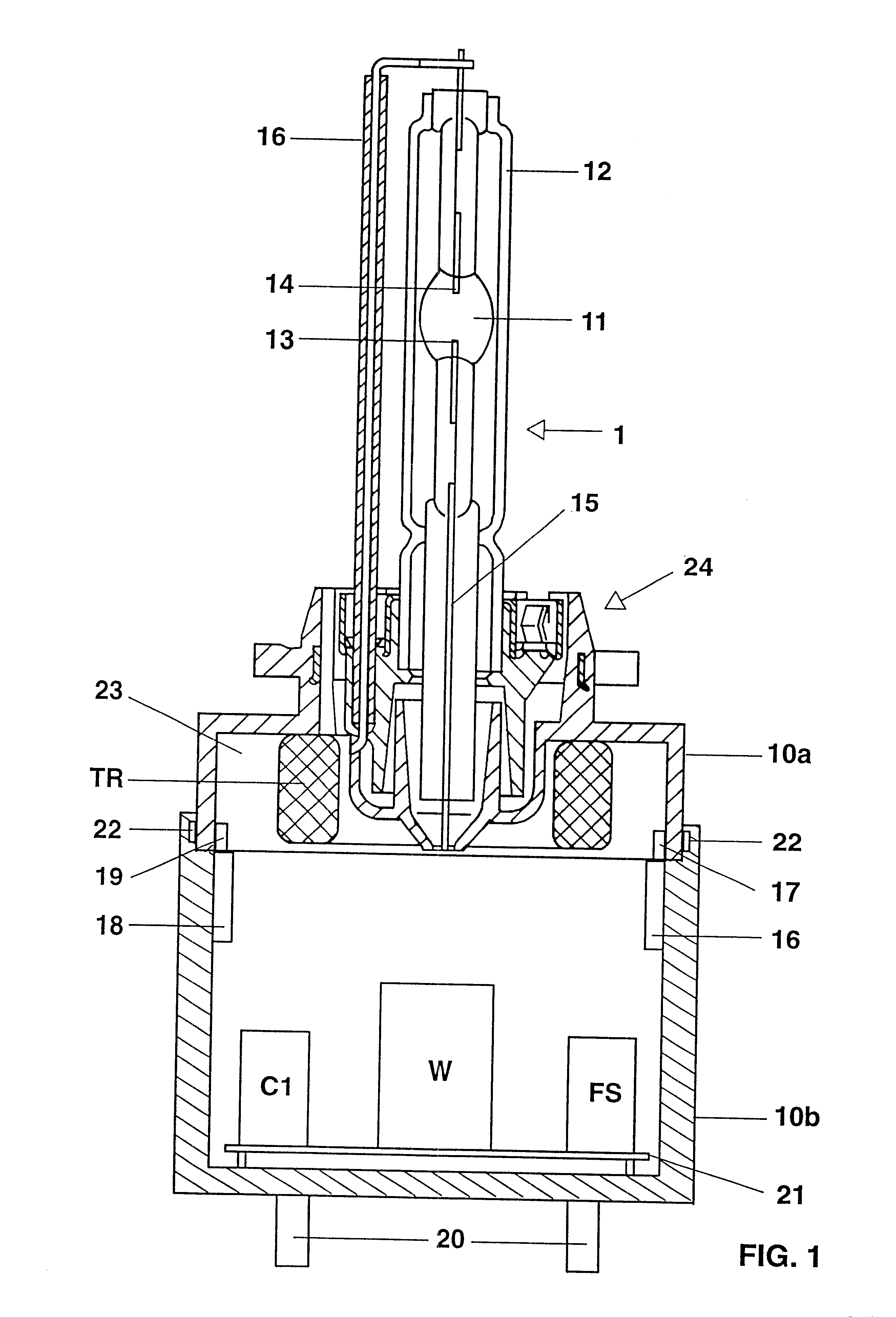
The further components of the ignition device, such as the ignition capacitor and the spark gap, are advantageously arranged in the second housing part. As a result, these components of the ignition device need not be replaced if the high-pressure discharge lamp is faulty. The further components of the ignition device are advantageously arranged on a support plate, which can easily be inserted into the second housing part. The at least two housing parts are advantageously connected to one another releasably by a snap-fit or screw-fit closure or by a plug connection. In addition, the first housing part advantageously has first electrical contacts and the second housing part has second electrical contacts, between which an electrically conductive connection is made when the first and the second housing part are connected to one another. The first and second electrical contacts of the housing parts advantageously form a plug connection which is produced automatically when the at least two housing parts of the base are fitted. This ensures that the lamp base is easy to assemble.
At least one housing part of the base is advantageously fitted with a cooling device which dissipates heat generated by the control unit. In addition, the first and / or the second housing part are shielded against electromagnetic radiation, which improves the electromagnetic compatibility of the lighting system according to the invention.
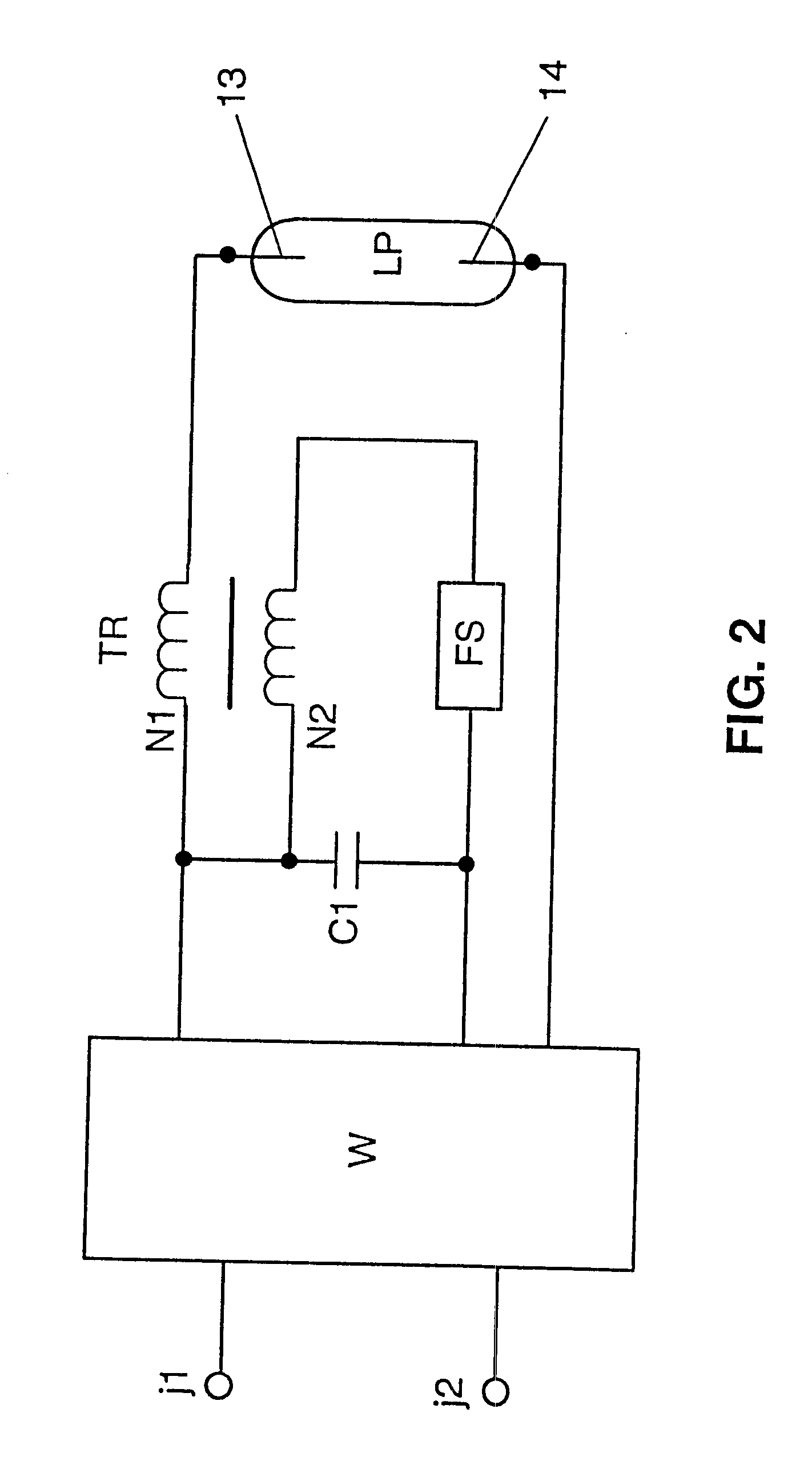
The control unit in the lighting system according to the invention has, in addition to the ignition device, a voltage converter which is advantageously designed as an inverter, for example as a half-bridge or full-bridge inverter, as a push-pull inverter or as a single-ended converter. This voltage converter is advantageously arranged on the same support plate as the aforementioned further components of the ignition device. This means that the whole control unit for the high-pressure discharge lamp can be accommodated in the base of the lamp. The arrangement is particularly compact and advantageous if the aforementioned voltage converter is designed as an integrated circuit.

Problems solved by technology

However, since the control unit is inseparably integrated in the lamp base, it cannot continue to be used if the lamp is faulty, but has to be replaced together with the faulty lamp.

Method used


Image

  • Lighting system with a high-pressure discharge lamp
  • Lighting system with a high-pressure discharge lamp
  • Lighting system with a high-pressure discharge lamp

Examples


Embodiment Construction

The object of the invention is to avoid the disadvantage of the lighting system according to the prior art.

The invention achieves this object as a result of the distinguishing features of patent claim 1. Particularly advantageous refinements of the invention are described in the subclaims.

The lighting system according to the invention has a high-pressure discharge lamp and a control unit for the high-pressure discharge lamp, the high-pressure discharge lamp having at least one lamp vessel, electrodes and an illuminant for producing a gas discharge, as well as a base provided with electrical connections. The base additionally has fastening means for the at least one lamp vessel. The control unit has an ignition device which is accommodated in the base and has a high-voltage part. According to the invention, the base has at least two housing parts, which are connected to one another by a releasable closure, the first housing part having the fastening means for the at least one lamp ve...


PUM


Abstract

The invention relates to a lighting system with a high-pressure discharge lamp and a control unit (W, FS, C1, W) for the high-pressure discharge lamp (1), where the lamp base (10) has at least two housing parts (10a, 10b) which are connected to one another by a releasable closure (22). The first housing part (10a) has fastening means (24) for the at least one lamp vessel (11). The high-voltage part (TR) of the ignition device (TR, FS, C1) is accommodated in the first housing part (10a), whilst the second housing part (10b) is provided with the electrical connections (20) for the high-pressure discharge lamp (1) and preferably contains the remaining components (FS, C1) of the ignition device and the voltage converter (W) of the control unit.

Description

The invention relates to a lighting system according to the preamble to patent claim 1.I. PRIOR ARTSuch a lighting system is disclosed, for example, in German Laid-Open Specification DE 196 10 385 A1. This document describes a high-pressure discharge lamp for motor vehicle headlamps, which has a lamp vessel of glass, two electrodes and a lamp base provided with electrical connections. A control unit for the high-pressure discharge lamp is integrated in the lamp base. The control unit usually has a considerably longer service life than the high-pressure discharge lamp. However, since the control unit is inseparably integrated in the lamp base, it cannot continue to be used if the lamp is faulty, but has to be replaced together with the faulty lamp.II. DESCRIPTION OF THE INVENTIONThe object of the invention is to avoid the disadvantage of the lighting system according to the prior art.The invention achieves this object as a result of the distinguishing features of patent claim 1. Part...

Claims


Application Information

Patent Timeline
IPC IPC(8): F21V15/00F21V19/00F21V15/06H01J5/00H01J61/56H01J61/02H01J5/54H05B41/04H05B41/00F21S8/10H01J5/50F21V23/00F21V29/15H01J61/54H01J61/82H01R33/945H05B41/02
CPCF21S48/1109F21S48/1186F21S48/325H01J5/54H01J61/56H05B41/042H01J61/54H01J61/82F21S41/192F21S45/47F21S45/48
Inventor HIRSCHMANN, GUENTHERGOTCHEV, BONTCHORUPP, ARNULF
Owner OSRAM SYLVANIA INC
Learn More