

Ultrasonic injection mold for an optical disk
an injection mold and optical disk technology, applied in the field of ultrasonic injection molds for optical disks, can solve the problems of defective products with shrinkage deformation and/or birefringence that cannot be manufactured, defective products with uniform filling, and fixed mold parts
- Summary
- Abstract
- Description
- Claims
- Application Information
AI Technical Summary
Benefits of technology
Problems solved by technology
Method used
Image

Examples
first embodiments
THE FIRST EMBODIMENTS
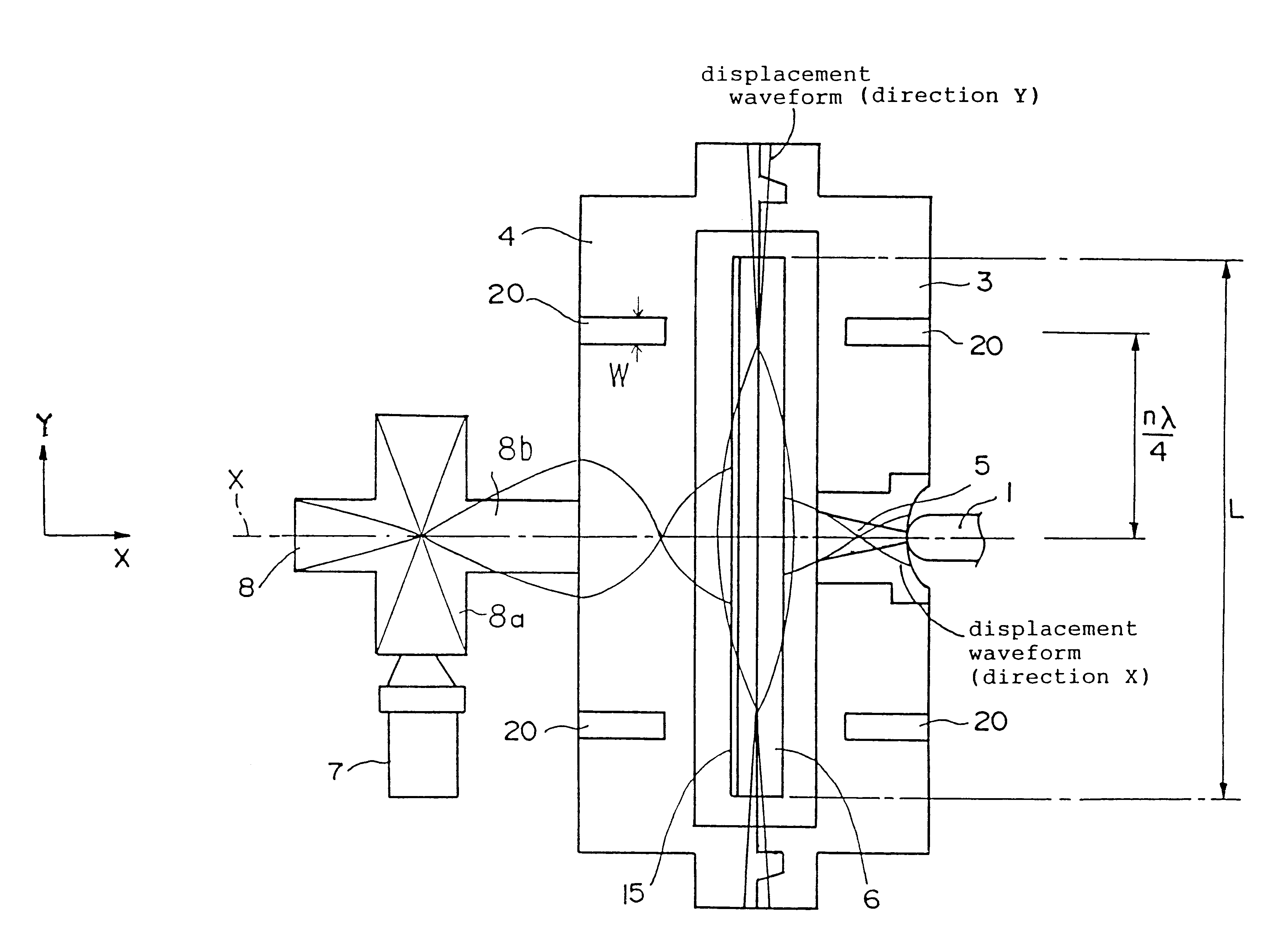
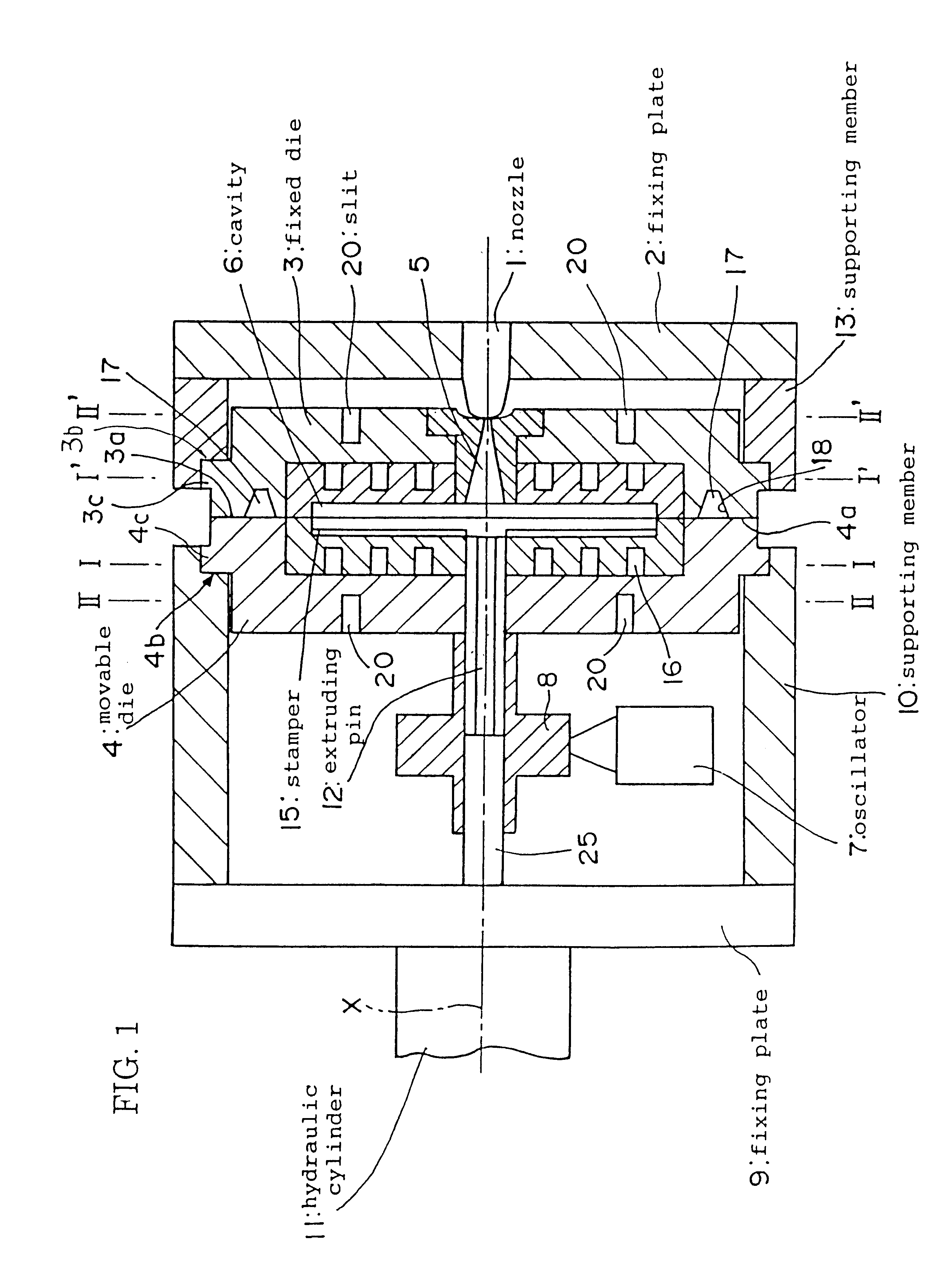
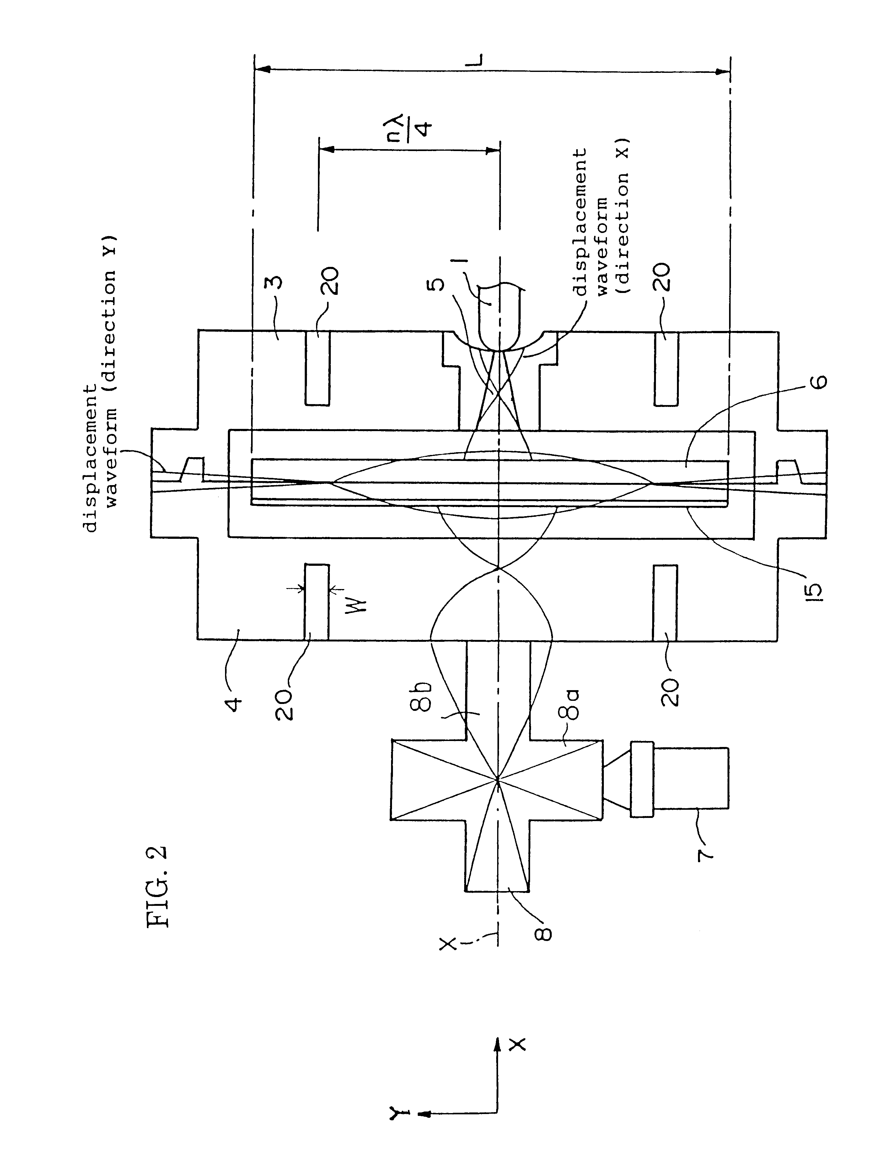
FIG. 1 is a partially cross-sectional schematic view of an ultrasonic injection mold for an optical disk in accordance with a first embodiment of the present invention. FIG. 2 is a diagram explaining a displacement waveform to be transferred within the mold of FIG. 1.
The injection molding machine to which the ultrasonic injection mold for an optical disk in accordance with the present invention can be applied includes all the ultrasonic injection mold for an optical disk wherein resin in the melted state is compressed into the mold, the resin is molded into a shape corresponding to that of the cavity, and taking it out of the mold.
In this injection molding machine in accordance with this embodiment, the fixed die 3 and the movable die 4, which will soon be described in details, are first clamped with no loads attached. Then, melted resin is injected from the nozzle 1 under a high pressure into the cavity 6 so that the fixed die 3 and the...
second embodiment
The second embodiment of the present invention will now be described by referring to FIG.5 and FIG. 6.
FIG. 5 is a partially cross-sectional schematic view of an ultrasonic injection mold for an optical disk in accordance with a second embodiment of the present invention and FIG. 6 is an enlarged view of a portion of the ultrasonic injection mold for an optical disk where a slit is provided.
In this second embodiment, the portions provided with the slits 20 on the surface of the fixed die 3 and the movable die 4 are supported by the supporting members 30.
As in the fixed die 3 and the movable die 4, if the slits 20 are formed on the sides opposite from the regions where the cavity 6 is formed, then the amplitude of the oscillations may be effectively lowered in the radial direction. Since the thickness of the portions where the slits 20 are formed will thus be smaller, the fixed die 3 and the movable die 4 will tend to be more readily deflected because of the internal pressure of the c...
example
Some experimental results will now be explained using comparative examples, wherein an ultrasonic injection mold for an optical disk in accordance with the second embodiment of the present invention is employed.
(1) The maximum and minimum values of the deflection is measured in the second embodiment under such conditions wherein the supporting members 30 are provided as shown in FIG. 5, the faucet method is employed as the guidance method in clamping and separating the fixed die 3 and the movable dies 4, and the ultrasonic with the frequency of 19 KHz is outputted from the oscillator. The results are as follows:
The internal pressure of the mold: 5.5 MPa
The deflection of the mold: Maximum: 7 .mu.m; Minimum: 1 R
(2) The maximum and minimum values of the deflection is measured as a third comparative example under such conditions wherein the guidance method is the same as above, the supporting members 30 are provided, and no ultrasonic is outputted. The results are as follows:
The third e...
PUM
| Property | Measurement | Unit |
|---|---|---|
| Distance | aaaaa | aaaaa |
| Area | aaaaa | aaaaa |
| Distance | aaaaa | aaaaa |
Abstract
Description
Claims
Application Information