Robot, robot system, and robot control method

a robot and control method technology, applied in the field of robots, can solve the problems of increasing the cost of cable preparation, increasing the number of cables correspondingly, and increasing the cost of cables. , to achieve the effect of raising costs

Inactive Publication Date: 2002-10-15
PANASONIC CORP
View PDF11 Cites 126 Cited by
  • Summary
  • Abstract
  • Description
  • Claims
  • Application Information

AI Technical Summary

Benefits of technology

It is an object of the present invention to provide a robot, a robot system, and a robot control method, which is capable of synchronizing with other robots, capable of performing a logical operation for input / output information, and capable of exchanging data information without raising costs.
According to this structure, since the history of the state of the robot is output to the network, a management apparatus connected to the network can use the history information and restore the production line into a correct working condition even when the robot installed in the production line stops by some factor.

Problems solved by technology

However, disadvantageously, if the number of pieces of equipment to be connected increases, the number of cables increases correspondingly, and, if the distance between pieces of equipment increases, that, of the cables increases correspondingly.
Accordingly, a problem resides in that a space is required to dispose the cables in the factory, and the cost of preparation of the cables rises.
Accordingly, a problem resides in that the cost of connection between the pieces of equipment goes up, or much time is consumed in programming the programmable logic controller.
Accordingly, a problem resides in that, when a large amount of data information is exchanged between the pieces of equipment of the production line or when information about the factors of errors caused by, for example, the breakdown of the equipment is exchanged between the pieces of equipment, a dedicated apparatus and a dedicated cable are required, and the installation cost rises.

Method used


Image

  • Robot, robot system, and robot control method
  • Robot, robot system, and robot control method
  • Robot, robot system, and robot control method

Examples


embodiment 1

(Embodiment 1)

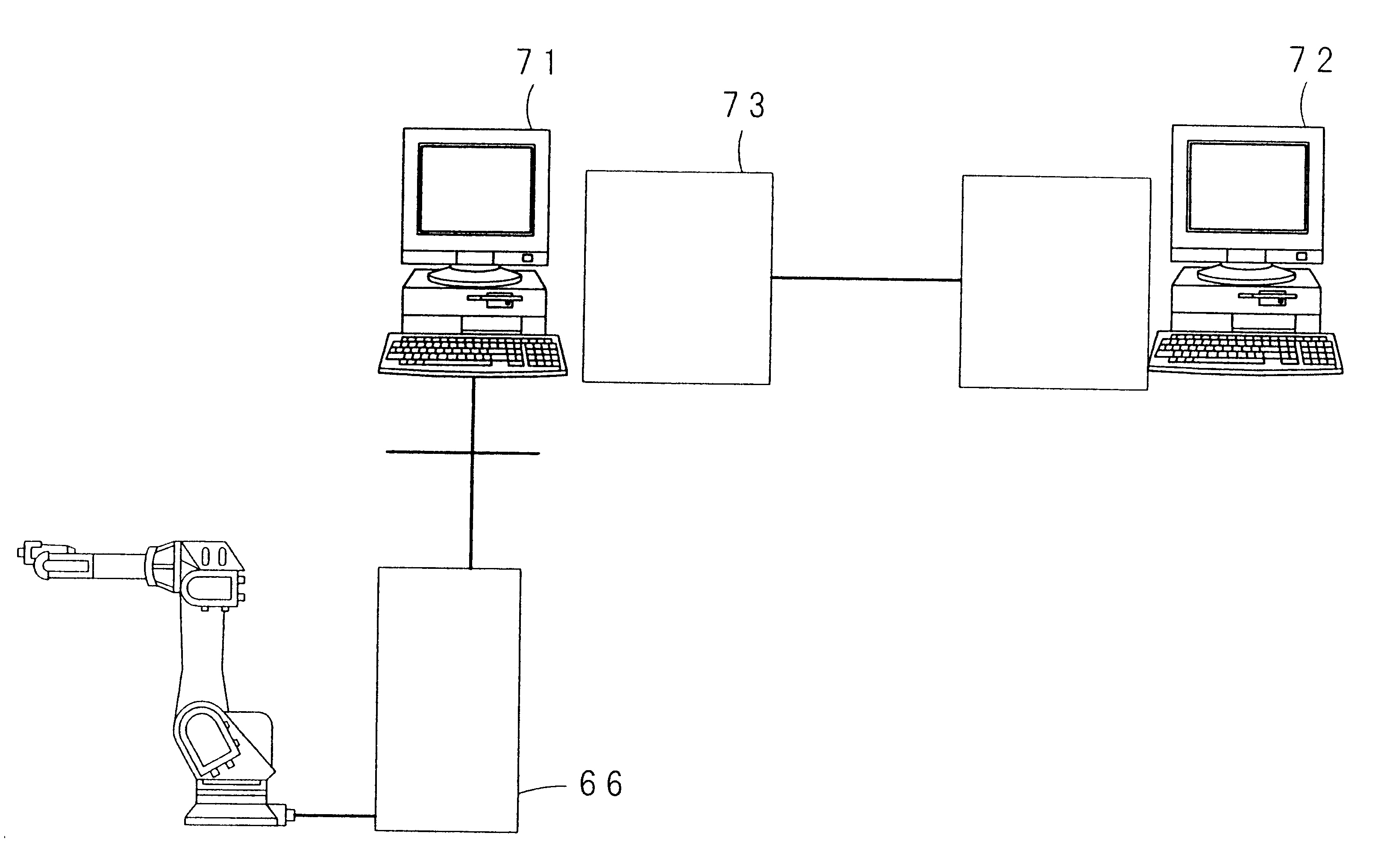
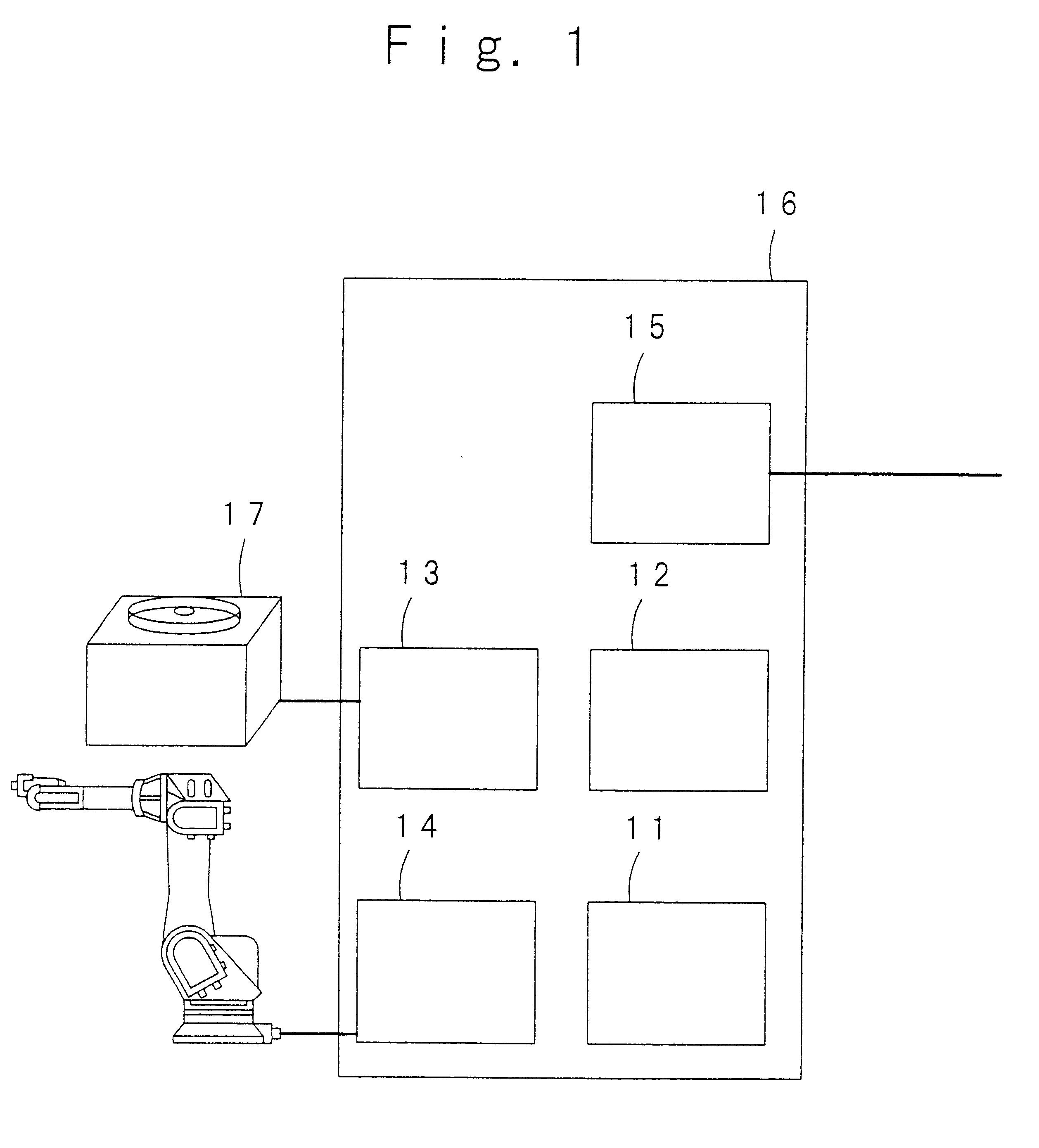
A first embodiment of the present invention will be described with reference to FIG. 1. FIG. 1 shows the basic structure of an industrial robot that realizes the first embodiment of the present invention. In FIG. 1, reference numeral 11 designates a storage portion in which an operating program of the robot is stored, reference numeral 12 designates a main arithmetic portion by which the operating program stored in the storage portion 11 is analyzed, reference numeral 13 designates a sequencer portion for outputting a signal from the main arithmetic portion 12 and informing the main arithmetic portion 12 about an input from an external apparatus 17, reference numeral 14 designates a driving portion for driving the robot on the basis of a signal from the main arithmetic portion 12, and reference numeral 15 designates a communications portion for communicating with an apparatus connected to a network. Reference numeral 16 designates a controller that includes the storage...

embodiment 2

(Embodiment 2)

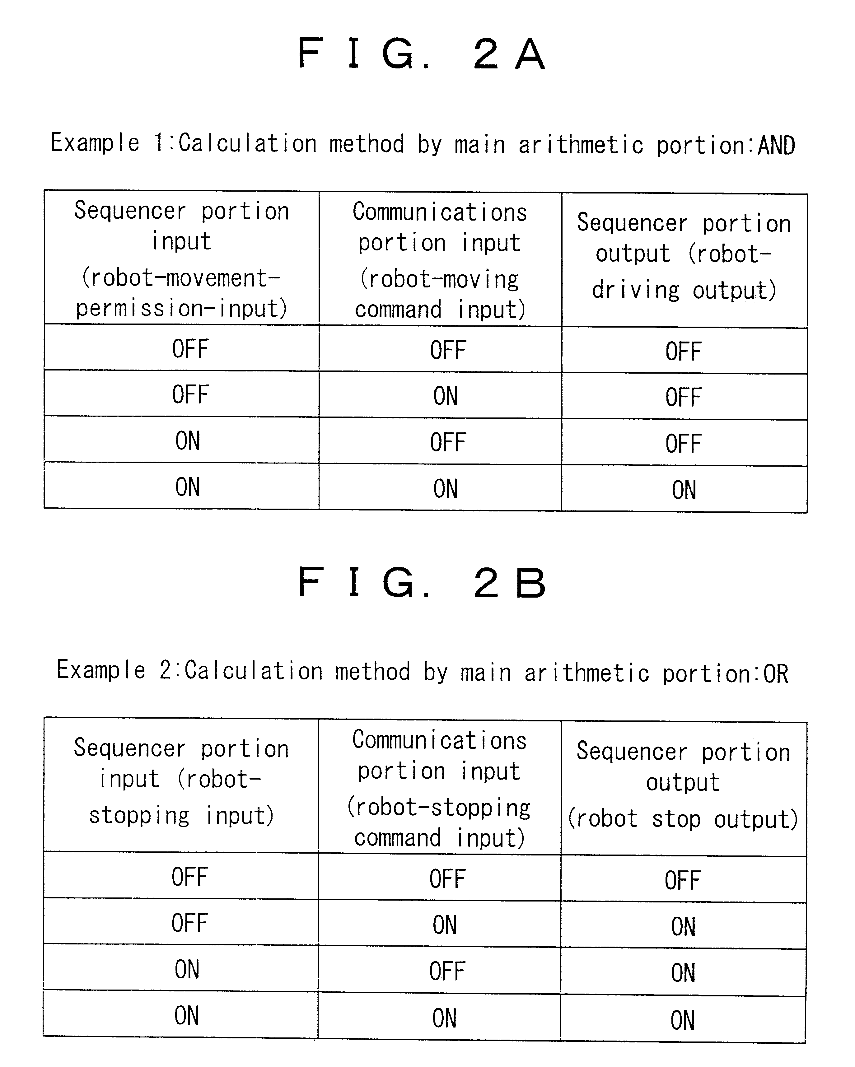
A second embodiment of the present invention will be described with reference to FIG. 2. Example 1 of (a) of FIG. 2 shows that a calculation method used in the main arithmetic portion 12 of the first embodiment is an AND operation. Even when a robot-moving command is transmitted from the network to the robot as an ON-signal through the communications portion 15, robot-driving output is turned on by the robot-moving command from the network only when robot-movement-permission-input is given as an ON-signal by the sequencer portion 13. The robot-movement-permission-input given by the sequencer portion 13 may be given by an operator or may be given by other external apparatuses connected to the robot.

When the operator must temporarily enter the working space of the robot for some reason, all that is needed is to turn the robot-movement-permission-input off. If so, the robot-driving output is not turned on even if a robot-moving command is sent from the network, and the ro...

example 2

of (b) of FIG. 2 shows that the calculation method used in the main arithmetic portion 12 is an OR operation. When either a robot-stopping command from the network or robot-stopping-input given by the sequencer portion 13 is turned on or when both of them are turned on, the robot-driving output is turned off. The robot-stopping-input given by the sequencer portion 13 may be given by the operator, or may be given by other external apparatuses connected to the robot.

When the operator wants to stop the robot for some reason, or when the controller that manages. the entire production line stops the robot because of an abnormality of other apparatuses, either of the stopping commands is turned on to stop the robot.

As mentioned above, the robot inputs a signal that has been input from the external apparatus 17 connected to the sequencer portion 13 to the sequencer portion 13 and a signal that has been input to the communications portion 15 to the main arithmetic portion 12, thereafter per...


PUM


Abstract

A robot for synchronizing with other robots without raising costs, a robot system, and a robot control method. The robot includes a storage portion (11) in which an operating program for the robot is stored, a main arithmetic portion (12) for analyzing the operating program stored in the storage portion, a sequencer portion (13) from which a signal from the main arithmetic portion is output, a driving portion (14) for driving the robot to which the signal from the main arithmetic portion (12) is input, and a communications portion (15) for communicating with apparatuses connected to a network. In the robot, a signal input from an apparatus connected to the sequencer portion (13) and a signal input to the communications portion (15) are input to the main arithmetic portion (12) so as to perform a calculation, and, based on the calculation, a signal is output from the main arithmetic portion (12) to the sequencer portion (13) or to the driving portion (14).

Description

This invention relates to a robot, a robot system, and a robot control method in which a robot is connected to a network, and the functions of robot input / output, robot control, failure diagnosis, maintenance, etc., are performed via the network.Conventionally, one or more industrial robots have been installed in a factory or in other similar buildings so as to perform the welding, conveyance, and assembly of components of products. In recent years, with the systematization and efficiency improvements in manufacturing environments such as that of a factory, cases have increased in which a medium-or large-scale production line is formed, and a plurality of industrial robots are installed as equipment for carrying out manufacture and inspection so as to construct a 24-hour operation of a mechanized production line in a manufacturing environment. In that case, as a robot-installing method, a method is employed in which the robot is installed in the vicinity of the production line of a ...

Claims


Application Information

Patent Timeline
Patent Type & Authority Patents(United States)
IPC IPC(8): B25J9/16G05B19/418G05B19/414B25J9/22B25J9/18B25J19/06
CPCB25J9/1682G05B19/414G05B19/4185G05B2219/31089G05B2219/33187G05B2219/36542G05B2219/39102G05B2219/39122G05B2219/39448G05B2219/40307Y02P90/02
Inventor IKEDA, TATSUYAFUJIKI, HISATOMISHINDO, AKIO
Owner PANASONIC CORP
Why Eureka
Try Eureka