Method and system for counting events within a simulation model

a simulation model and event counting technology, applied in the field of interactive design and simulation of complex circuits and systems, can solve the problems of large investment in simulation, high cost and time-consuming segment of the overall design process, and the inability to accurately and accurately simulate the circuit and system. to ensure the highest possible accuracy and efficiency in the process used

Inactive Publication Date: 2002-10-22
GLOBALFOUNDRIES INC
View PDF20 Cites 104 Cited by
  • Summary
  • Abstract
  • Description
  • Claims
  • Application Information

AI Technical Summary

Benefits of technology

The above and other objects are achieved as is now described. A method and system are disclosed that utilize the expressiveness of hardware description languages for efficiently and comprehensively monitoring performance characteristics of a digital circuit design during simulation. According to the present invention, a design entity that is part of a digital circuit design is first described utilizing a hardware description language. Next, a counting instrument is described utilizing the same hardware description language. The counting instrument is designed to detect occurrences of a count event within the design entity during simulation of the digital circuit design. The counting instrument is associated with the design entity utilizing a non-conventional call, such that the counting instrument may be utilized to monitor each instantiation of the design entity within the simulation model without the instrumentation entity becoming incorporated into the digital circuit design. In association with the counting instrument, a linear feedback shift register is automatically generated for recording the number of occurrences of the count event within the design entity.

Problems solved by technology

As logic networks become highly complex, it becomes a necessary to simulate a design before the design is actually built.
This is especially true when the design is implemented as an integrated circuit, since the fabrication of integrated circuits requires considerable time and correction of mistakes is quite costly.
Simulation has become a very costly and time-consuming segment of the overall design process as designs become increasingly complex.
Therefore, great expense is invested to ensure the highest possible accuracy and efficiency in the processes utilized to verify digital designs.
A problem arises however when the overall model is simulated as a whole.
Compound errors may occur which mask other individual errors.
Further, the enormity of modern digital design complexity makes the errors in each design entity difficult to recognize.
Therefore, although the hierarchical nature of VHDL eases the development and modeling phases of complex designs, problems with obtaining accurate and comprehensive simulation test results of the overall design remain unresolved.
This method of "end-to-end" checking has two problems.
First, the problem of masking of internal logic failures remains as these errors may not propagate to the final results of the circuit checked in an end-to-end test.
Second, an end-to-end check may fail to catch an intermediate failure that occurred during the simulation run but was masked or overwritten by a later action in the simulation run.
A problem associated with this method, however, is that it adds further complexity to the simulation process by requiring an extra communication step between designers and simulation programmers.
The efficiency and effectiveness of the simulation testing are therefore reduced.
Another problem with utilizing verification programs written in languages such as C++ or C is that these programs are not amenable to execution on a hardware simulator.
Such stoppages usually have a dramatic negative impact on the performance of hardware simulators.

Method used


Image

  • Method and system for counting events within a simulation model
  • Method and system for counting events within a simulation model
  • Method and system for counting events within a simulation model

Examples


Embodiment Construction

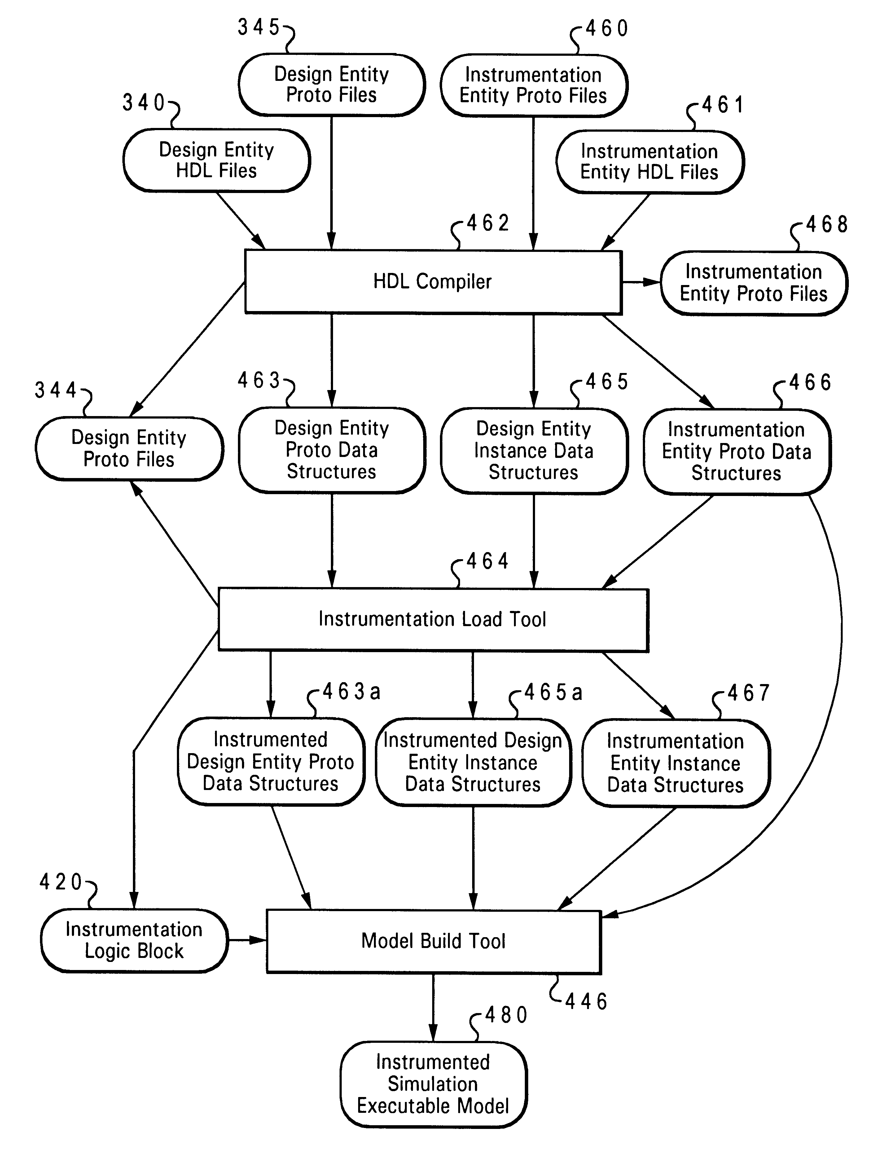
The present invention accomplishes the goal of accurately and comprehensively monitoring the operation of a digital circuit design by allowing for designer creation of instrumentation modules in the same hardware description language (HDL) as utilized for the design. HDLs, while suited to the needs of digital designers can also be effectively utilized for a number of checking functions. By allowing a digital designer to utilize the HDL to create checking and instrumentation modules, the need to learn a language such as C or C++ is eliminated. These instrumentation modules will be utilized to monitor specified design parameters while not becoming an integral part of the design itself. Furthermore, since these instrumentation modules are written in the same HDL as utilized in the actual design, such modules are platform and simulator independent. Unlike checking done with C or C++ programs, HDL instrumentation can be compiled and run directly without loss of performance on hardware si...


PUM


Abstract

A method and system that utilize the expressiveness of hardware description languages for efficiently and comprehensively monitoring performance characteristics of a digital circuit design during simulation. According to the present invention, a design entity that is part of a digital circuit design is first described utilizing a hardware description language. Next, a counting instrument is described utilizing the same hardware description language. The counting instrument is designed to detect occurrences of a count event within the design entity during simulation of the digital circuit design. The counting instrument is associated with the design entity utilizing a non-conventional call, such that the counting instrument may be utilized to monitor each instantiation of the design entity within the simulation model without the instrumentation entity becoming incorporated into the digital circuit design. In association with the counting instrument, a linear feedback shift register is automatically generated for recording the number of occurrences of the count event within the design entity.

Description

1. Technical FieldThe present invention relates in general to a method and system for interactively designing and simulating complex circuits and systems, particularly digital devices, 1modules and systems. In particular, the present invention relates to a method and system that utilize instrumentation modules written in hardware description language to monitor the operation of computer-generated digital circuit designs. More particularly, the present invention relates to an improved counting method by which events detected by HDL instrumentation entities may be counted without the need for excess incrementation logic.2. Description of the Related ArtVerifying the logical correctness of a digital design and debugging the design, if necessary, are very important steps in most digital design processes. Logic networks are tested either by actually building networks or by simulating networks on a computer. As logic networks become highly complex, it becomes a necessary to simulate a des...

Claims


Application Information

Patent Timeline
Patent Type & Authority Patents(United States)
IPC IPC(8): G01R31/3183G01R31/317G01R31/28G06F17/50
CPCG01R31/31704G01R31/318357G06F17/5022G06F30/33
Inventor BARGH, JOHN FOWLERROESNER, WOLFGANGWILLIAMS, DEREK EDWARD
Owner GLOBALFOUNDRIES INC
Why Eureka
Try Eureka