Cutting tool having liquid-spraying nozzles for controlling chip formation

a technology of liquid spraying and cutting tools, which is applied in the direction of shaping cutters, turning machine accessories, manufacturing tools, etc., can solve the problems of tangled chips developing, and achieve the effect of improving chip breaking ability

Inactive Publication Date: 2002-10-29
SANDVIK INTELLECTUAL PROPERTY AB
View PDF8 Cites 69 Cited by
  • Summary
  • Abstract
  • Description
  • Claims
  • Application Information

AI Technical Summary

Benefits of technology

is to provide a cutting tool, which not only guarantees a

Problems solved by technology

This is something that in practice means th

Method used


Image

  • Cutting tool having liquid-spraying nozzles for controlling chip formation
  • Cutting tool having liquid-spraying nozzles for controlling chip formation

Examples


Embodiment Construction

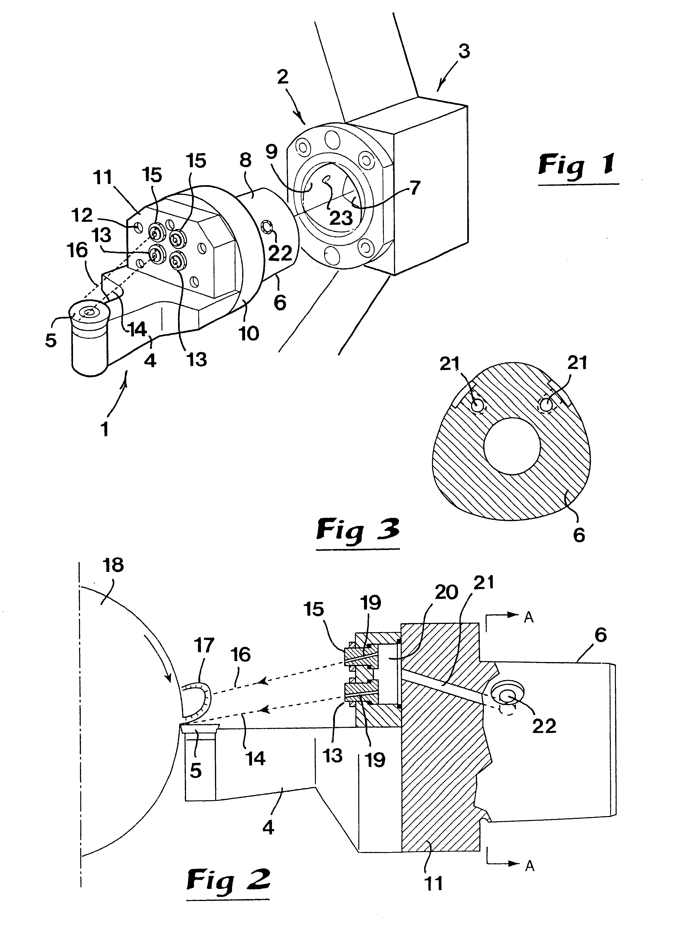
In the drawing, a cutting tool is generally designated 1, which in the example is included in a so-called modular tool system and co-operates with a clamping unit 2. This clamping unit is fixedly assembled in a machine 3 outlined only partially, which is represented by a portion of a turret plate.

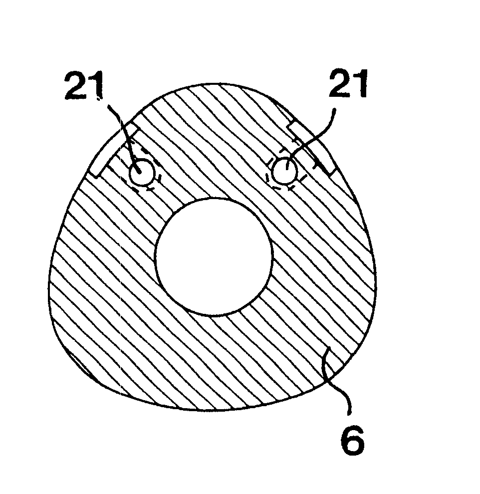
The cutting tool 1 includes a front part 4 with a detachable cutting insert 5, which in the example is in the form of a round cutting insert. A rear part 6 of the cutting tool is in the shape of a male element, which is insertable in a cavity 7 in the clamping unit 2. The coupling between the cutting tool and the clamping unit may advantageously be of the COROMANT CAPTO.RTM. type, the male element 6 as well as the cavity 7 having a polygonal, although softly rounded cross-section shape, which tapers in the backward direction. In the area of the interior of the cavity 7, there is a clamping mechanism (not shown) which may be brought to engagement with coupling means (not shown) inside the ma...


PUM

PropertyMeasurementUnit
Pressureaaaaaaaaaa
Pressureaaaaaaaaaa
Pressureaaaaaaaaaa

Abstract

A metal workpiece is cut by rotating the workpiece while pressing the cutting edge of a cutting insert thereagainst for removing a chip from the workpiece. A first liquid jet is directed from a first nozzle toward an upper surface of the cutting insert for creating an hydraulic wedge between the cutting insert and the chip, and a second liquid jet is directed from a second nozzle toward a target point disposed above the upper surface of the cutting insert to engage and deflect the chip upwards and backwards.

Description

This invention relates to a cutting tool including a tool body with, on the one hand, a front part for holding a cutting insert and, on the other hand, a rear part, which houses a plurality of nozzles. The nozzles are supplied with pressurized cooling liquid from an external liquid supply source via a duct system inside the tool body for the purpose of spraying a high pressure cooling liquid jet towards the area of an upper surface on the cutting insert in a manner forming an hydraulic wedge between the upper surface of the cutting insert and a chip emanating from a workpiece, in order to lift and distance the chip from the cutting insert.GENERAL BACKGROUND OF THE INVENTION AND PRIOR ARTIt is a common practice to cool not only the cutting inserts of cutting tools, e.g. Tools for turning, but also to cool the workpiece (which commonly comprises metal which is to be machined by the tool), as well as to cool the chips which are cut from the workpiece. A fundamental aim in today's techn...

Claims


Application Information

Patent Timeline
IPC IPC(8): B23Q11/00B23Q11/10B23B27/10
CPCB23Q11/005B23Q11/10B23B27/10Y10T407/116Y10T407/11Y10T407/14B23B27/22
Inventor LAGERBERG, STIG
Owner SANDVIK INTELLECTUAL PROPERTY AB
Why Eureka
Try Eureka