Heat-resistant anti-attrition high-strength milling cutter blade for heavy cutting
A high-strength, milling blade technology, applied in the direction of milling cutting blades, milling cutters, milling machine equipment, etc., can solve the problems of tool wear, loss of tool change, large and frequent cutting parameters, etc.
- Summary
- Abstract
- Description
- Claims
- Application Information
AI Technical Summary
Problems solved by technology
Method used
Image
Examples
specific Embodiment approach 1
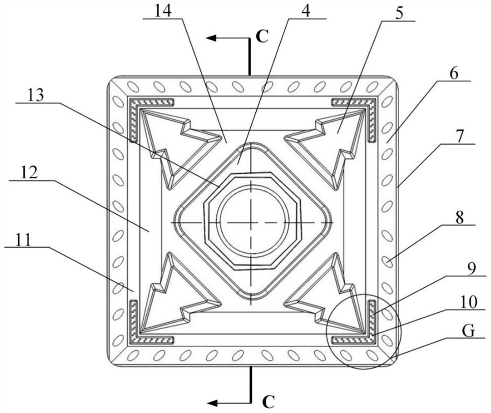
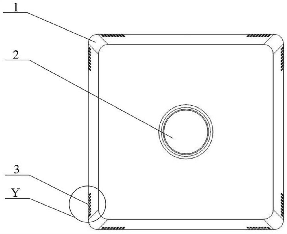
[0021] Specific implementation mode one: combine figure 1 , figure 2 , image 3 , Figure 4 , Figure 5 , Image 6 and Figure 7 As shown, a heat-resistant and wear-reducing high-strength milling insert for heavy-duty cutting, the insert body is in the shape of a square truss. The insert has a double rake angle structure, the cutting edge is provided with a negative chamfer structure, and a circular arc edge (1) transition is provided between two adjacent negative chamfer cutting edges (7); The boss (4), the center of the quadrilateral boss (4) is machined with fastening screw holes (2) for connecting with the milling cutter disc along the thickness direction of the blade; the upper surface of the quadrilateral boss (4) is fastened with screw holes (2) Cooling grooves (13) are arranged on the outer periphery, and the cooling grooves (13) are octagonal in shape.
specific Embodiment approach 2
[0022] Specific implementation mode two: combination figure 1 As shown, the first rake face (6) of the blade is provided with elliptical wear-reducing protrusions (8) in different directions, and the distance between the long axis of the elliptical wear-reducing protrusion (8) and the negative chamfer cutting edge (7) It forms an included angle of 45°, and when the main deflection angle of 45° is formed during the cutting process, the direction of the major axis of the elliptical wear-reducing protrusion (8) is the same as the feeding direction of the blade. The undisclosed technical features in this embodiment are the same as those in the first embodiment.
specific Embodiment approach 3
[0023] Specific implementation mode three: combination figure 1 , figure 2 , Image 6 and Figure 7 As shown, there is a transition plane (11) parallel to the bottom surface of the blade connecting the first rake face (6) and the second rake face (12). A micro-groove (10), the micro-groove (10) has a right-angle structure; the micro-groove (10) is provided with a right-angled double-row distributed circular micro-groove texture (9). The micro-groove (10) can reduce the friction in the knife-chip contact area, reduce the temperature, force and stress in the knife-chip contact area, and the circular micro-groove texture (9) can effectively alleviate the bonded wear of the tool. The undisclosed technical features in this embodiment are the same as those in the first embodiment.
PUM
 Abstract
Description
Claims
Application Information
 - R&D
- Intellectual Property
- Life Sciences
- Materials
- Tech Scout
- Unparalleled Data Quality
- Higher Quality Content
- 60% Fewer Hallucinations
Browse by: Latest US Patents, China's latest patents, Technical Efficacy Thesaurus, Application Domain, Technology Topic, Popular Technical Reports.
© 2025 PatSnap. All rights reserved.Legal|Privacy policy|Modern Slavery Act Transparency Statement|Sitemap|About US| Contact US: help@patsnap.com


