

Optical recording medium
a recording medium and optical technology, applied in the field of optical recording mediums, can solve the problems of high error rate of address signals, low intentity of prepit signals, high jitter and block error rate,
- Summary
- Abstract
- Description
- Claims
- Application Information
AI Technical Summary
Problems solved by technology
Method used
Image

Examples
embodiment 1
(Embodiment 1)
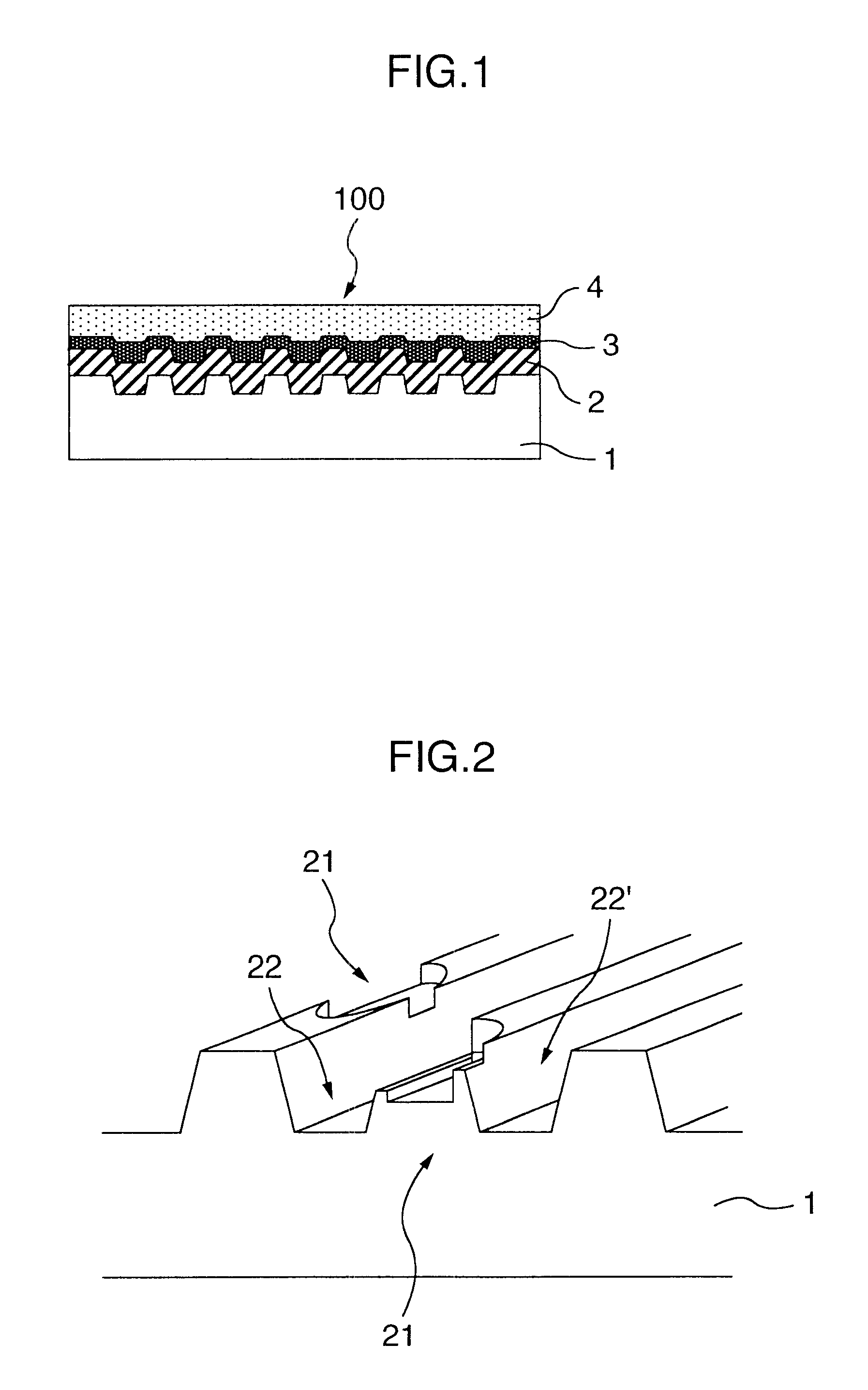
Referring to FIG. 1 which is a schematic sectional view illustrating a write-once type optical recording medium according to the present invention, the write-once optical recording medium 100 is composed of an optical transparent substrate 1 on which an optical absorbing layer 2, an optical reflecting layer 2 and a protecting layer 4 are successively formed. Explanation will be hereibelow made of a method of manufacturing this write-once optical recoding medium 100.
At first, a glass master adapted to be used for manufacturing an optical transparent substrate was manufactured as follows;
First, a polished flat grass substrate was prepared, and the glass substrate is coated thereover with a photoresist adapted to act on ultraviolet radiation, by a predetermined thickness. As to the photoresist, there was used a mixture of polymer of cresol novolak resin and a photosensitizer of naphthoquinon diazido. Then, the glass substrate was set on a turn table in an exposure deice w...
embodiment 2
(Embodiment 2)
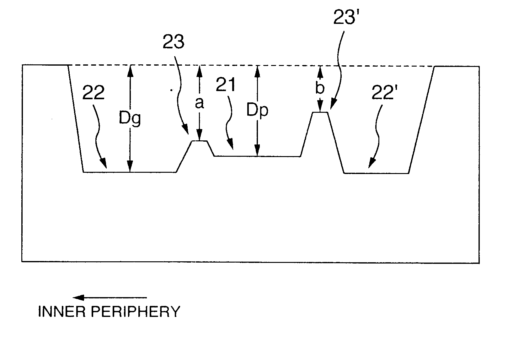
There was manufactured a write-once type recording medium similar to that of the embodiment 1, except that, referring to FIG. 3, the maximum depth Dg of the pregrooves 22 was 175 nm, the maximum depth Dp of the prepits 21 was 170 nm, the depth a of the edge parts on the inner side of the pit 22 was 35 nm, and the depth b of the edge parts 23' on the outer side of the prepits 21 was 35 nm, and that, the length A of the edge parts 23 on the inner peripheral side of the prepits 21 was 96 nm in the direction of the pregrooves 22, and the length B of the edge parts 23' on the outer peripheral side of the prepit 21 was 96 nm in the direction of the pregrooves 22'.
The write-once type recording medium 100 was irradiated thereonto with a leaser beam having a wavelength of 635 nm and a power of 8 mW so as to record thereon image data. The error rate of address signals was 0.8% before the recording, but the error rate of address signals becomes 1.8% after the recording, which is ...
embodiment 3
(Embodiment 3)
There was manufactured a write-once type recording medium similar to that of the embodiment 1, except that, referring to FIG. 3, the maximum depth Dg of the pregrooves 22 was 182 nm, the maximum depth Dp of the prepits 21 was 92 nm, the depth a of the edge parts 23 on the inner side of the prepits 22 was 85 nm, and the depth b of the edge parts 23' on the outer side of the prepits 21 was 80 nm, and that, the length A of the edge parts 23 on the inner peripheral side of the prepits 21 was 310 nm in the pregroove direction, and the length B of the edge part 23' on the outer peripheral side of the prepits 21 was 304 nm in the pregroove direction.
The write-once type recording medium 100 was irradiated thereonto with a leaser beam having a wavelength of 655 nm and a power of 9 mW so as to record thereon image data. The error rate of address signals was 0.9% before the recording, but the error rate of address signals becomes 2.2% after the recording, which is satisfactory. T...
PUM
| Property | Measurement | Unit |
|---|---|---|
| wavelength | aaaaa | aaaaa |
| wavelength | aaaaa | aaaaa |
| depth | aaaaa | aaaaa |
Abstract
Description
Claims
Application Information