Micro-hardness measurement method and micro-hardness meter

a micro-hardness and measurement method technology, applied in the direction of mechanical measuring arrangements, instruments, using mechanical means, etc., can solve the problems of underestimating the hardness of the surface area of permanent depression, difficult to read the diagonal length of the indentation by using an optical type microscope, and inability to obtain the hardness of only the film, etc., to achieve excellent operability, excellent versatility, and simple operation of the hardness calculation

Inactive Publication Date: 2007-07-12
RENIASU
View PDF10 Cites 27 Cited by
  • Summary
  • Abstract
  • Description
  • Claims
  • Application Information

AI Technical Summary

Benefits of technology

[0071]According to the present invention, it is possible to provide a micro-hardness measurement method which, since the load data when loading and the unloading data when unloading are extracted and the virtual depth δv is calculated based on these data, does not require any cumbersome operation that carries out correction by measuring the depth of the indentation and the length of the diagonal line thereof a plurality of times and calculating the correction value, and which may calculate the hardness with simple operations and is excellent in operability.
[0072]It is possible to provide a micro-hardness measurement method that is excellent in versatility and is able to calculate the hardness of either a test sample such as metals in which deflection is unlikely to occur or a test sample in which deflection is likely to occur such as a test sample in which a hard surface layer is formed on the surface of a substrate.
[0073]It is possible to provide a micro-hardness measurement method that almost accurately obtains the inclination of a tangent line at depth δ1 of the load curve and the inclination of a tangent line at the maximum depth δ0 of the unloading curve since the load curve and the unloading curve in the vicinity of the maximum depth δ0 are comparatively simple, wherein an error is unlikely to occur, and is able to calculate the hardness at high accuracy without being influenced by the profile of an indenter.
[0074]It is possible to provide a micro-hardness measurement method that is excellent in applicability and is able to calculate the hardness of a test sample having such a hard surface layer, on which only a micro load is permitted to be loaded, and only a micro indentation whose diagonal line length is 10 micrometers or less is permitted to be formed since it is not necessary to measure the actual depth of an indentation and the actual length of the diagonal line of an indentation.
[0075]According to the present invention, in addition to the effects discussed above, it is possible to provide a micro-hardness measurement method that is able to simplify setting of the first permissible range, has high detection sensitivity, wherein an error is unlikely to occur, and is able to measure the hardness at high accuracy since it is judged, in the first judging step, whether or not a conversion value n0 / m0 of the ratio of the inclinations n0 and m0 of tangent lines exceeds the upper limit of the first permissible range.
[0076]According to the present invention, in addition to the effects discussed above, it is possible to provide a micro-hardness measurement method that is able to simplify setting of the second permissible range, has high detection sensitivity, wherein an error is unlikely to occur, and is able to measure the hardness at high accuracy since it is judged, in the second judging step, whether or not a conversion value n1 / m1 of the ratio of the inclinations n1 and m1 of tangent lines exceeds the upper limit of the second permissible range.

Problems solved by technology

However, where the hardness of a test sample in which a hard film is formed on the surface of a substrate, there was a problem that the hardness of only the film cannot be obtained since influences on the hardness of the substrate are exerted or an indenter penetrates the film.
In addition, since the depression depth of the indentation is made equivalent to the thickness of the film and the indentation is influenced by the substrate, there was another problem that it is difficult to read the diagonal length of the indentation by using an optical type microscope.
However, since, in the depression depth measurement system, a test sample is deflected if an indenter is forcedly pushed therein where the elastic deformation ratio of the test sample is great when forming an indentation, the push-in depth of the indenter is made greater than the depth of the indentation (permanent depression), wherein the surface area of a depression calculated from the push-in depth of the indenter becomes greater than the surface area of the indentation (permanent depression) after the load is unloaded, and there is still another problem that the hardness calculated by the (maximum load) / (surface area of permanent depression) is underestimated.
However, the following problems in the prior art described above exist.
Therefore, there is a problem that the operation is very cumbersome.
He-5-20691, an error occurs when calculating the proportional constant K and the dynamic hardness of a test sample by means of the least squares method, and there is another problem that the measurement accuracy is lowered.
Therefore, where the hardness is calculated in regard to a test sample the hardness of which changes in the depth direction as in a test sample in which a hard surface layer is formed on the surface of a soft substrate, there is still another problem that the error becomes remarkably large, depending on the push-in depth of the indenter.
In the art disclosed by Japanese Published Unexamined Patent Application No. 2001-349815, since an error occurs when the relationship of the ratio of hardness to elastic modulus of various materials is linearly approximated, and the error is accumulated when calculating the hardness, there is still another problem that the measurement accuracy is lowered.
Also, since the hardness H is obtained by a calculation equation of H=Pmax / A from the maximum load Pmax and the contact area A of an indenter at the maximum load, the art is a hardness measurement method aiming at metal materials the test sample of which is unlikely to be deflected and elastically deformed, and there is a problem that the method is short of applications.

Method used


Image

  • Micro-hardness measurement method and micro-hardness meter
  • Micro-hardness measurement method and micro-hardness meter
  • Micro-hardness measurement method and micro-hardness meter

Examples


embodiment 1

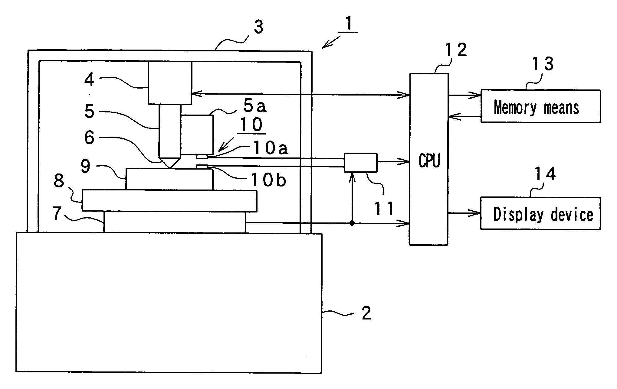
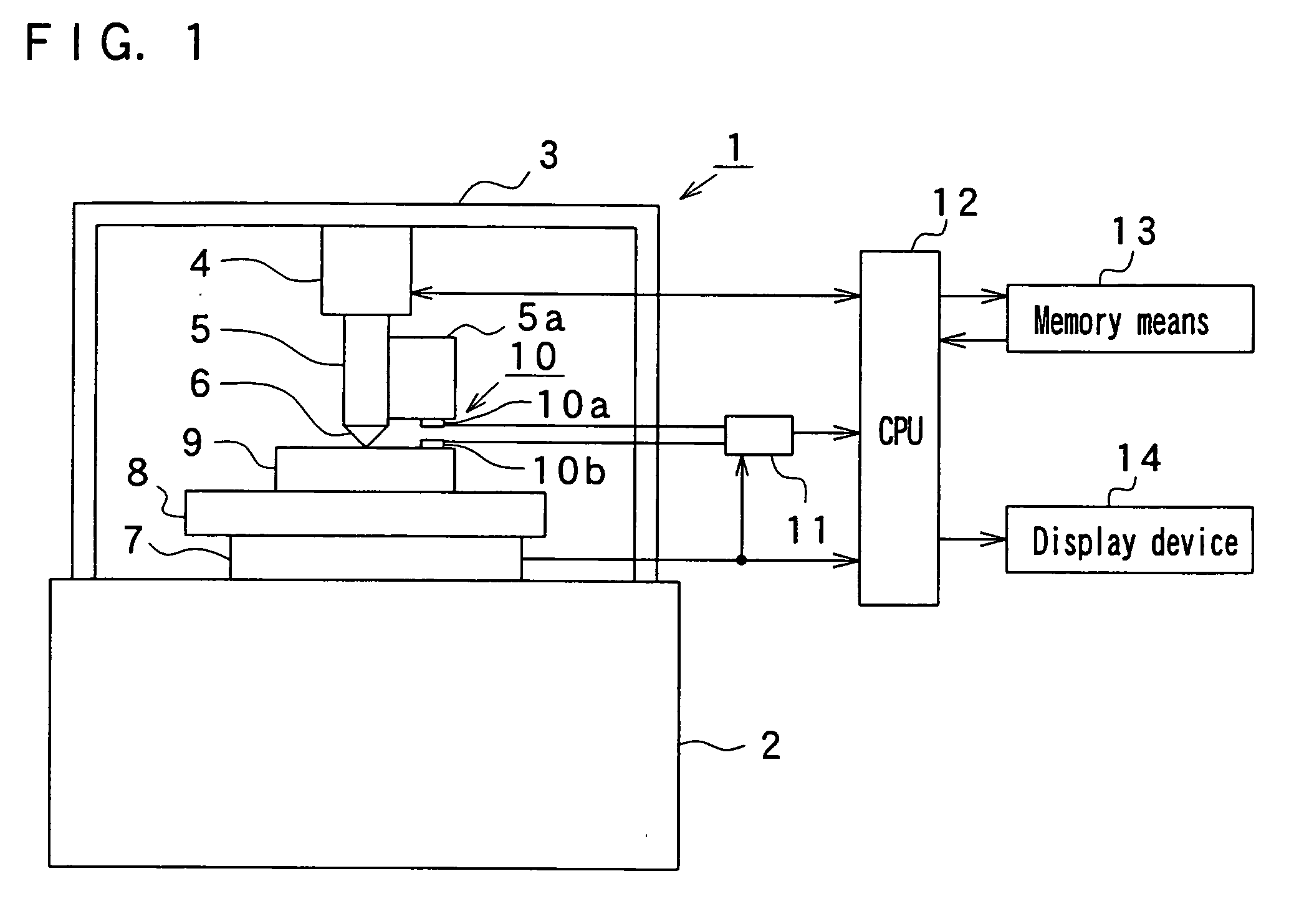
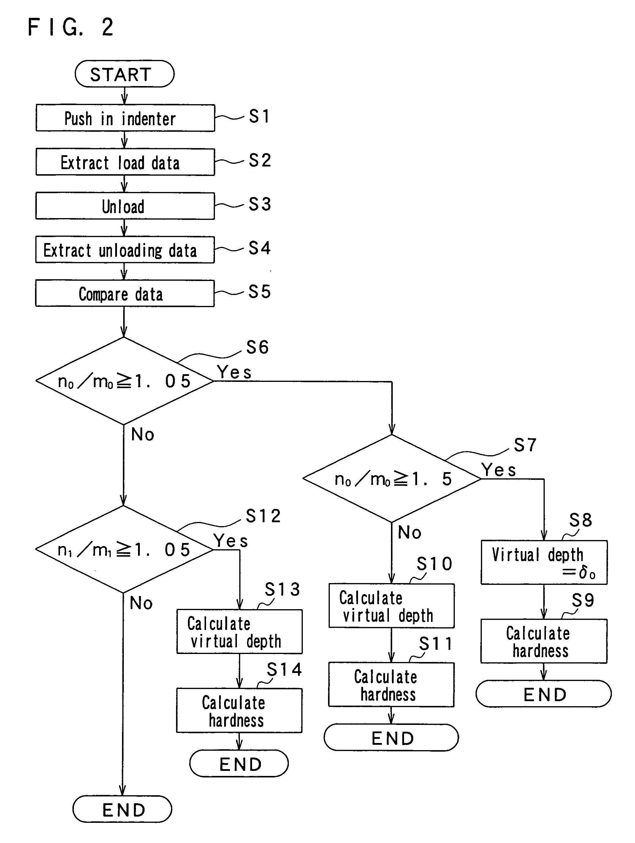
[0088]FIG. 1 is a block diagram depicting a micro-hardness meter according to one embodiment of the invention, FIG. 2 is a flowchart depicting actions of the micro-hardness meter, and FIG. 3 and FIG. 4 are views depicting the calculation principle of virtual depth δv.

[0089]In FIG. 1, reference numeral 1 denotes a micro-hardness meter according to one embodiment of the invention, 2 denotes a base portion of the micro-hardness meter 1, 3 denotes a frame body erected on the base portion 2, and 4 denotes a load device composed of a piezoelectric actuator and a stepping motor, etc., which is able to increase and decrease the load given to an indenter 6 vertically suspended from the frame body 3 and described later at an optional speed. Reference numeral 5 denotes an indenter support vertically suspended from the load device 4, 5a denotes an extension portion extending sideways of the indenter support 5 and vertically moving along with the indenter support 5, 6 denotes a Vickers or Knoop ...

example 1

[0121]The hardness of a test sample in which a hard glass layer 5 through 10 micrometers thick is formed on the surface of a polycarbonate substrate (10 millimeters thick) was measured by using the micro-hardness meter described in one embodiment.

[0122]The test sample was placed on the stage and a Vickers indenter was pushed in from the surface of the test sample at a rate of 0.2 micrometers per second. After being loaded to the maximum load (the established test force) L0=109 mN, the maximum load L0 was retained for 15 seconds, and next the load of the indenter was unloaded. Finally, the indenter was pulled up from the test sample at the rate of 0.2 micrometers per second same as that when loading.

[0123]FIG. 5 is a view showing the load data, load curve, unloading data, unloading curve and virtual depth δv in Example 1. The abscissa thereof shows the depth and the ordinate thereof shows the load. White circles show actually measured load data while black circles show actually measu...


PUM

PropertyMeasurementUnit
diagonal lengthaaaaaaaaaa
lengthaaaaaaaaaa
hardnessaaaaaaaaaa

Abstract

A micro-hardness measurement method for calculating the hardness of a test sample by pushing an indenter in the test sample and forming an indentation thereon, including: a loading step for extracting load data showing the relationship between load L applied to the indenter and a depth δ to which the indenter is pushed in from the surface of the test sample; an unloading step of extracting unloading data showing the relationship between the load L applied to the indenter after the load is unloaded and the depth δ; a first step of judging, by comparing the unloading data with the load data, the load fluctuation amount from the maximum depth δ0 when unloading the load; and a second step of judging the load at the depth δ1 10) when unloading the load or the load fluctuation amount in the vicinity of the depth δ1.

Description

CROSS-REFERENCE TO RELATED APPLICATIONS[0001]This application claims priority from Japanese Patent Appln. No. 2006-001892, filed Jan. 6, 2006, the contents of which are herein incorporated by reference in their entirety.BACKGROUND OF THE INVENTION[0002]1. Field of the Invention[0003]The present invention relates to a micro-hardness measurement method for measuring the hardness of a test sample by forming an indentation or impression by pushing an indenter into a test sample, and a micro-hardness meter therefor, and in particular, to a micro-hardness measurement method and a micro-hardness meter, which are best suitable for calculating the hardness of a test sample in which a hard surface layer is formed on the surface of a soft substrate.[0004]2. Description of the Prior Art[0005]Conventionally, as a measurement method of the hardness, a diagonal length measurement system by which the hardness is obtained based on the length of a diagonal line of an indentation formed by an indenter...

Claims


Application Information

Patent Timeline
Patent Type & Authority Applications(United States)
IPC IPC(8): G01N3/48
CPCG01N3/42G01N2203/0676G01N2203/0051
Inventor ISOMOTO, YOSHINORI
Owner RENIASU
Why Eureka
Try Eureka