Surface plasmon resonance fiber sensor

a surface plasmon and fiber sensor technology, applied in the field of surface plasmon resonance fiber sensor, can solve the problems of inability to meet the needs of emergency management teams, easy to be damaged, and the conventional surface plasmon resonance sensing apparatus is almost zero tolerable to vibration, so as to shorten the detection time, improve the detection accuracy, and reduce noise. the effect of occurring

Inactive Publication Date: 2009-04-23
FORWARD ELECTRONICS CO LTD
View PDF8 Cites 26 Cited by
  • Summary
  • Abstract
  • Description
  • Claims
  • Application Information

AI Technical Summary

Benefits of technology

[0008]The object of the present invention is to provide a surface plasmon resonance fiber sensor, which can lower noise occurring during the detection operation, improve the accuracy of the detection, and have the following advantages: shortened detection time, pre-labeling on the DUT before the detection being not required, only a small amount of sample being required, on-line detection of the interaction between the DUT and the corresponding ligand being possible, and the sensitivity of the detection being high.
[0009]Another object of the present invention is to provide a surface plasmon resonance sensing apparatus, which is easily portable, easy to operate, has a bio-detecting unit that is easily exchangeable, and has lower detecting noise and higher detecting accuracy.

Problems solved by technology

However, since the size of the conventional surface plasmon resonance sensing apparatus is quite large, and for normal operation, the relative position relation between all of the elements thereof must be carefully maintained the same during the whole detection process, the conventional surface plasmon resonance sensing apparatus is almost zero-tolerated to the vibration and is easily destroyed by impact.
Therefore, the conventional surface plasmon resonance sensing apparatus is not suitable for an emergency management team to take to a site with them.

Method used


Image

  • Surface plasmon resonance fiber sensor
  • Surface plasmon resonance fiber sensor
  • Surface plasmon resonance fiber sensor

Examples


embodiment 1

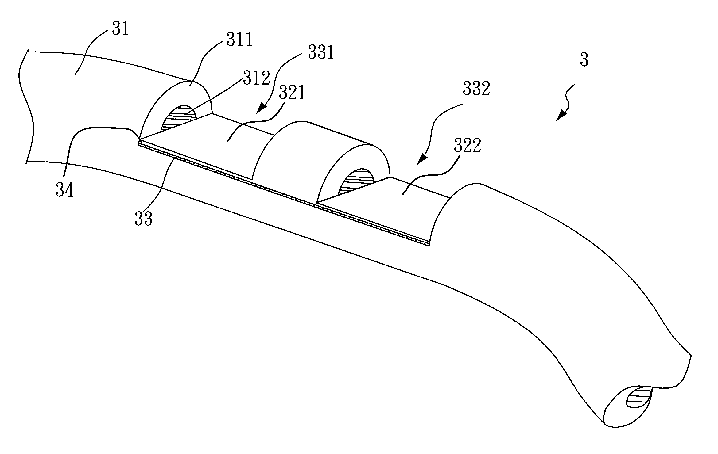
[0026]FIG. 3 is a schematic drawing of one preferred embodiment of a surface plasmon resonance fiber sensor according to the present invention. The surface plasmon resonance fiber sensor 3 comprises an optical fiber member 31, a first sensing unit 321, and a second sensing unit 322, wherein the optical fiber member 31 is a multi-mode fiber, and the first sensing unit 321 and a second sensing unit 322 are arranged in a cascade form matrix. Besides, the aforementioned optical fiber member and the optical fiber sensing units of the surface plasmon resonance fiber sensor 3 are integrated as a whole. In the present embodiment, the first sensing unit 321 and the second sensing unit 322 are formed by executing a polishing process on the optical fiber member 31. A first groove 331 and a second groove 332 are thus formed and arranged in a cascade form matrix, wherein the polishing length of each of these two grooves is about 0.5 mm. Moreover, the maximum depths of these two grooves are large...

embodiment 2

[0028]FIG. 4 is a schematic drawing of another preferred embodiment of a surface plasmon resonance fiber sensor according to the present invention. The surface plasmon resonance fiber sensor 4 comprises a first optical fiber member 41, a second optical fiber member 42, a first sensing unit 421, and a second sensing unit 422, wherein the first optical fiber member 41 and the second optical fiber member 42 are both multi-mode fibers, and the first sensing unit 421 and the second sensing unit 422 are formed on the first optical fiber member 41 and the second optical fiber member 42, respectively. Besides, the first sensing unit 421 and the second sensing unit 422 are arranged in a cascade form matrix. Being different from the previous embodiment, the aforementioned sensing units and the optical fiber members are connected through a welding process. In the present embodiment, the first sensing unit 421 and the second sensing unit 422 are formed by executing a polishing process on the fi...

embodiment 3

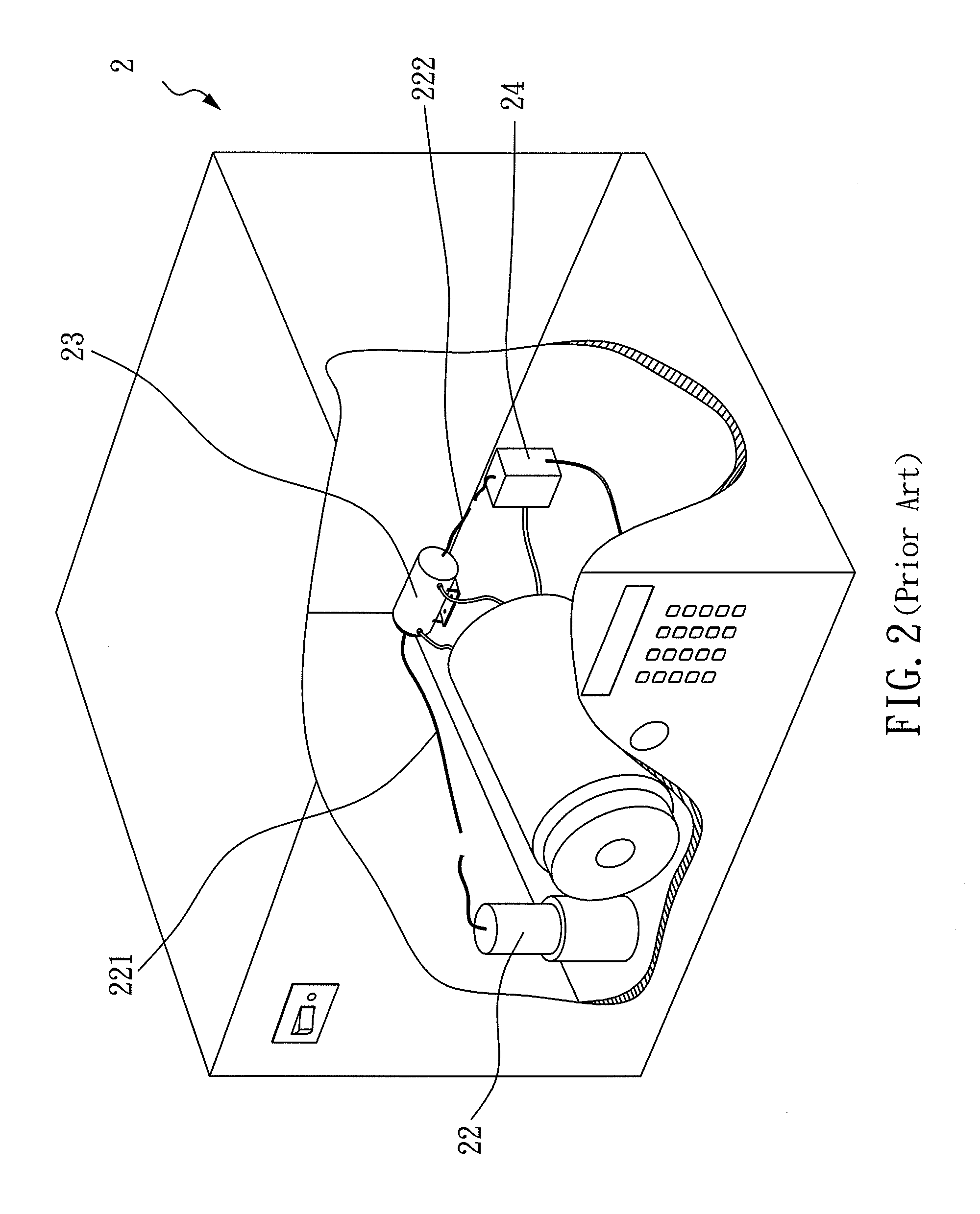
[0030]In the present embodiment, the surface plasmon resonance fiber sensor of the present invention is applied in a surface plasmon resonance sensing apparatus, wherein the surface plasmon resonance sensing apparatus can be the one being used in the prior art application. The surface plasmon resonance sensing apparatus of the present invention will be explained in the following, along with FIG. 2 of the present invention.

[0031]The surface plasmon resonance sensing apparatus of the present invention comprises a laser diode 22 as a light source, and the light emitted from the laser diode 22 is guided and incident into a sample tank 23 through a multi-mode fiber 221, wherein the surface plasmon resonance fiber sensor of the present invention (not shown) is installed in the sample tank 23. An optical signal detector 24 is connected with the optical fiber sensing unit (not shown) through another multi-mode fiber 222. The optical signal detector 24 transfers the light it received into co...


PUM

PropertyMeasurementUnit
lengthaaaaaaaaaa
thicknessaaaaaaaaaa
lengthaaaaaaaaaa

Abstract

A Surface Plasmon Resonance (SPR) fiber sensor is disclosed, which comprises an optical fiber member and a plurality of optical fiber sensing units. Each of the plurality of the optical fiber sensing units comprises a cladding layer, a core layer, and a groove, and the plurality of the optical fiber sensing units is arranged into a cascade form matrix. In each of the optical fiber sensing units, the cladding layer is located at the periphery of the core layer, and the maximum depth of the groove is larger than the thickness of the cladding layer. An SPR sensing apparatus is also disclosed, which includes a light source, an optical signal detector, a plurality of fibers, and a plurality optical fiber sensing units. Besides, the optical fiber sensing units, the light source, and the optical signal detector are connected with each other through the plurality of fibers.

Description

BACKGROUND OF THE INVENTION[0001]1. Field of the Invention[0002]The present invention relates to a surface plasmon resonance fiber sensor and, more particularly, to a surface plasmon resonance fiber sensor having plural optical fiber sensing units arranged into a cascade form matrix, wherein the surface plasmon resonance fiber sensor is easy to operate, easily portable, having higher resolution and analyzing sensitivity, and being able to be applied in a surface plasmon resonance sensing apparatus.[0003]2. Description of Related Art[0004]Currently, in the medical detecting field or environment detecting field, it is important to detect immediately and accurately the kind and the concentration of a biomolecule under test. For example, in a site having a leakage of hazardous material, it is extremely important for the emergency management team to on-site identify the kind of the hazardous material and the concentration thereof immediately and accurately, in order to determine which is...

Claims


Application Information

Patent Timeline
Patent Type & Authority Applications(United States)
IPC IPC(8): G02B6/00G01N21/00G01N21/27G01N21/41
CPCB82Y20/00G02B6/1226G01N2021/7736G01N21/553
Inventor TSAO, YU-CHIAYANG, YI-WENTAI, JOU-KAITSAI, WOO-HU
Owner FORWARD ELECTRONICS CO LTD
Why Eureka
Try Eureka