Eureka AIR delivers breakthrough ideas for toughest innovation challenges, trusted by R&D personnel around the world.

Multi-line station interface

a multi-line station and interface technology, applied in the field of interface devices, can solve the problems of high cost of installing a second telephone adjacent to an existing one, unfavorable customer preferences, and significant difficulties in reconfiguring the premises for multi-line services, and achieve the effect of reducing the cost and facilitating installation

Inactive Publication Date: 2002-11-05
TELEPORT COMM GROUP
View PDF10 Cites 29 Cited by
  • Summary
  • Abstract
  • Description
  • Claims
  • Application Information

AI Technical Summary

Benefits of technology

It is an object of the present invention to provide a multi-line interface device for providing multiple telephone line services to a home / office that is easy to install at a minimum cost.
Still another object of the present invention is to provide a multi-line interface device which makes cost savings decisions available to the consumer by allowing them to choose between service providers automatically to obtain the least cost routing of their calling needs.
Yet even further, an object of the invention is to provide a multi-line interface device which is for use with the evolving Hybrid Fiber Coax (HFC) networks being deployed by Multiple System Operators (MSOS) or Cable TV companies today. The integral use of fiber optic technology in the loop enables the network to be more reliable and secure versus the traditional copper based telephone plant.
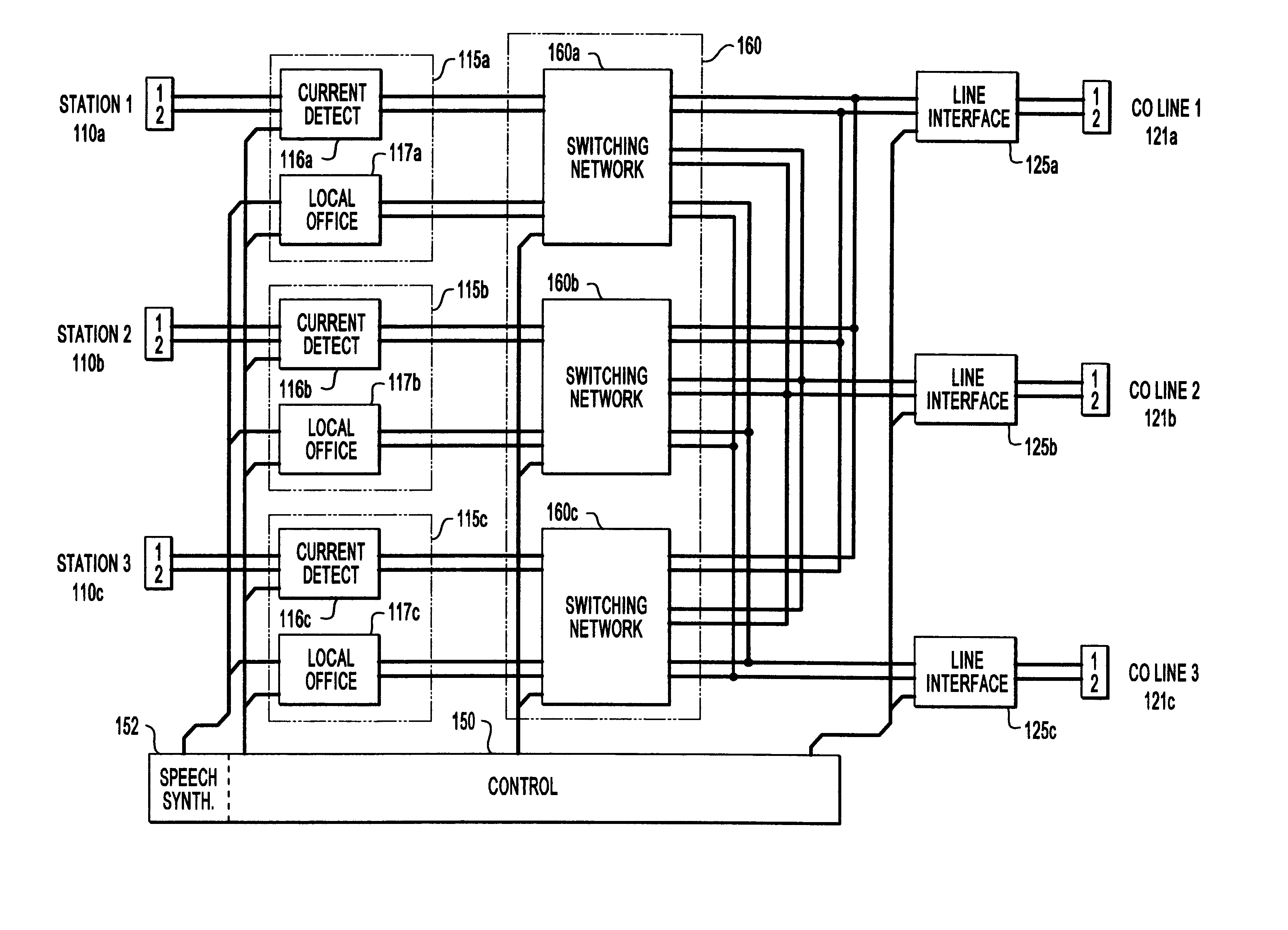
The control unit provides internal bridging of station access modules to the same access line module. In a private mode, the control unit prevents further connections and interruptions of a private connection between a station access module and an access line module. In response to a ring signal from one of the access lines, the control unit provides a ringing tone to all or selected stations which have no calls in progress, and optionally provides a line waiting tone to the stations which have calls in progress.

Problems solved by technology

Adding secondary telephone service to a residence or small business location ("premises") presents significant difficulties in reconfiguring the premises for the multi-line services.
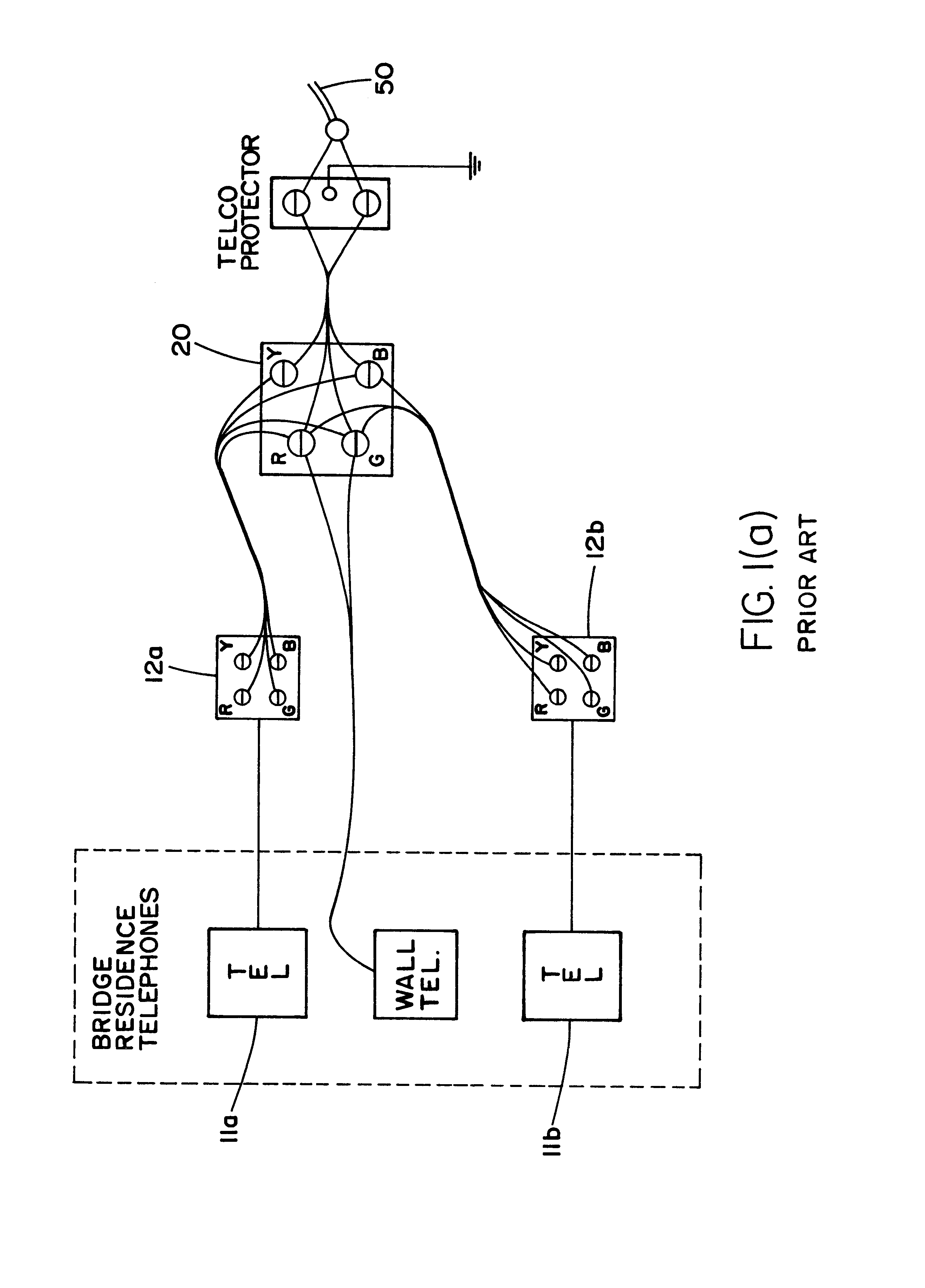
Consequently, the existing customer-owned inside wire and single line telephones will remain in place and the new service provider is faced with the dilemma of installing a new telephone(s) within the premises which would require additional telephone(s) and necessitate the rewiring of the premises.
Although the existence of quad wire may someday overcome some of the problems involved in providing multiple-line connections, it is very doubtful that continuity exists for the second line and rewiring is necessary at the phone demarc to intercept and redirect a spare pair of wires to the alternate service provider.
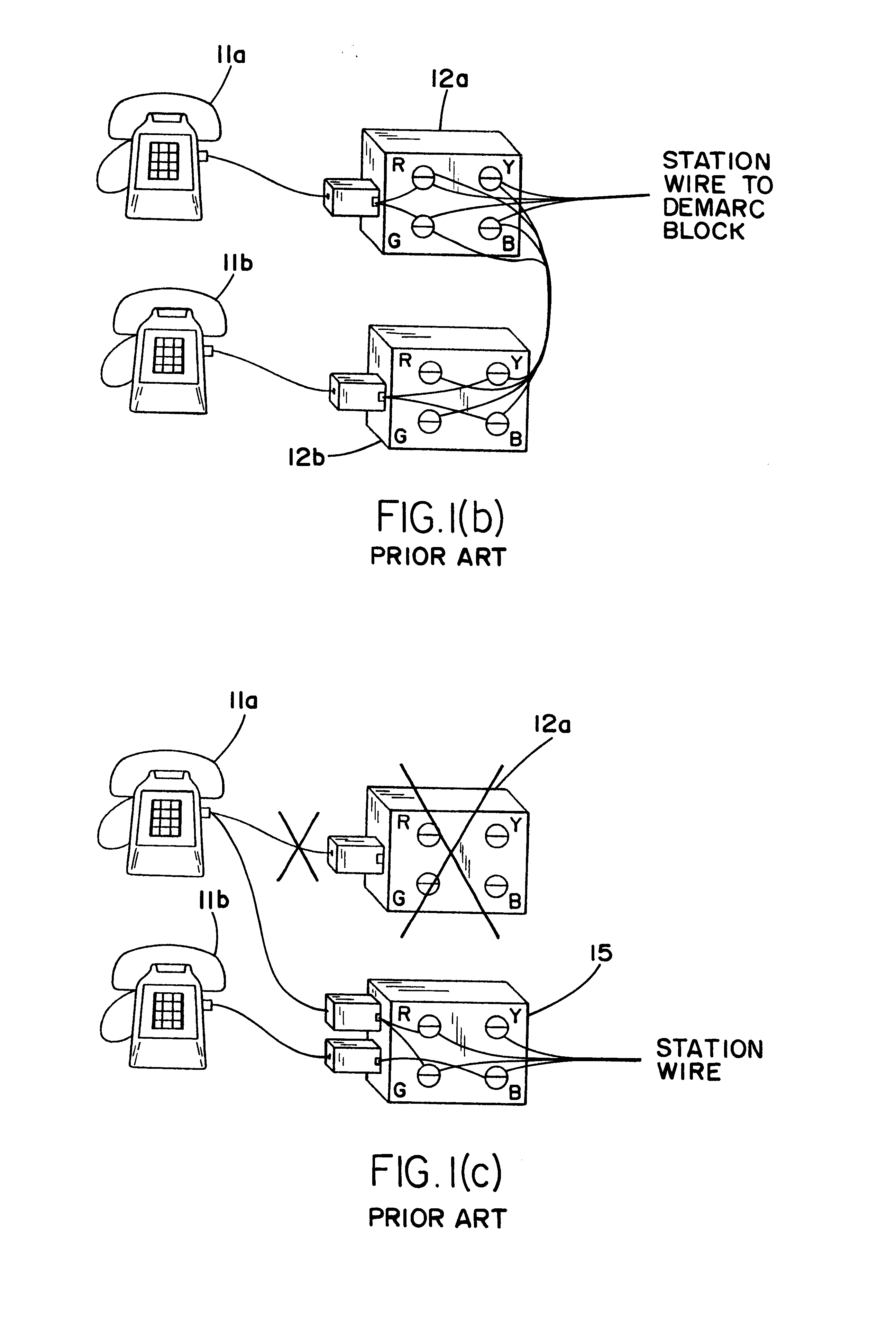
It is the case that the complexity of installing a second telephone adjacent to an existing one is both costly and not conducive to customers' preferences.
Rewiring within the customer premises, either to install an additional line or to change existing wiring with multi-line cables, involves a level of expense which most residential customers will not voluntarily change.
However, phone replacement costs are high and in the case of portables, very expensive.
Another adverse condition of rewiring or changing wall telephones is the potential for damage.
Inevitably, wallpaper is torn, painted areas are chipped, and, the replacement phone in all likelihood will not be in the old area.
In the case of wall phones, access to concealed wiring is necessary, which ultimately requires removing the phone to access the wiring in the wall and exposing the provider to potential damage claims.
The aforementioned solutions are not favorable to the customer and are costly to the new service provider.
This is due to the need to rewire and the associated cost involved in connecting the second line to EACH phone.

Method used


Image

  • Multi-line station interface
  • Multi-line station interface
  • Multi-line station interface

Examples


Embodiment Construction

FIG. 2 illustrates a physical view of the multi-line and station interface (MLSI) device 100 of the present invention. As explained above, the multi-line and station interface device 100 ("interface device") includes circuitry (explained in detail below) which is enclosed in high impact housing and which is easily installable in any accessible area adjacent to the present LEC (local exchange company) demarc block which is provided by an existing primary service provider. As shown in FIG. 2 and the functional diagram of FIG. 3, the circuitry for the interface device is powered by an interchangeable power converter module 130 on the circuit board. The selected module 130 is dependent upon two optional power sources. The first option is power available from the service terminating interface (DEMARC) at the service location. The line can be powered from a protected source and can provide 35-60 volt quasi square wave AC to the interface device on terminals 105. The second and preferable ...


PUM


Abstract

An interface device is disclosed for simultaneously connecting access lines to stations. Any one of the stations answers an incoming call from any one of the access lines. The interface device has line access modules each connected to a respective access line, and station access modules each connected to a respective station. A switching network selectively connects at least one of the line access modules to at least one of the station access modules. The switching network is controlled by a control unit in accordance with a predetermined sequence stored in the control unit or selected signals received from the stations through the station access modules. A speech synthesizer provides an audio signal to the stations indicating status the interface device, as well as available features and options of the interface device and the access lines. The control unit provides internal bridging of station access modules to the same access line module. In a private mode, the control unit prevents further connections and interruptions of a private connection between a station access module and an access line module. In response to a ring signal from one of the access lines, the control unit provides a ringing tone to all or selected stations which have no calls in progress, and optionally provides a line waiting tone to the stations which have calls in progress.

Description

FIELD OF THE INVENTIONThe present invention relates generally to interface devices for providing telephone services to customers, and in particular, to a multi-line interface device that enables an additional secondary phone service provider to provide telephone service to / from premises which are already furnished with telephone lines of an existing primary telephone service provider, the device being installed in the premises without the need to provide additional telephone devices, and, without the intrusion and necessity of significant rewiring.DESCRIPTION OF THE PRIOR ARTAdding secondary telephone service to a residence or small business location ("premises") presents significant difficulties in reconfiguring the premises for the multi-line services. For instance, there is a very strong probability that existing telephone services of a primary service provider or local exchange company ("LEC") will not be disconnected initially. Consequently, the existing customer-owned inside w...

Claims


Application Information

Patent Timeline
Patent Type & Authority Patents(United States)
IPC IPC(8): H04M1/64H04M1/00
CPCH04M1/738
Inventor BRUHNKE, HOWARDWILNER, ERIC J.REYNOV, BORIS
Owner TELEPORT COMM GROUP
Why Eureka
Eureka Blog
Learn More