
Method and apparatus for controlling an industrial robot

a robot and industrial technology, applied in the direction of programme control, mechanical control devices, distance measurement, etc., can solve the problem that the robot cannot achieve high motor moments, and achieve the effect of much more simple and fast programming

Inactive Publication Date: 2002-11-05
ABB (SCHWEIZ) AG
View PDF17 Cites 22 Cited by
  • Summary
  • Abstract
  • Description
  • Claims
  • Application Information

AI Technical Summary

Benefits of technology

The present invention aims at providing a technique which solves the above mentioned problems in teach-in and which at the same time makes the programming much more simple and faster, in particular in applications such as assemblage, disassembly and advanced material handling.
With this technique, the object will fully follow the intentions of the operator without the operator having to keep a check on relations between for instance control stick directions and the movement direction / rotation axle of the object. When the object is to touch its surroundings, which is always the case during assemblage, the robot can never obtain to high motor moments, since the moment will decrease instead of increase during interaction between object / robot and the surroundings. Furthermore, the operator does not have to see the whole object, on the contrary, by means of interaction between the object and the surroundings, he can get assistance in finding the correct way for the movement of the object.
An apparatus for controlling the reference values to the axle servo of a robot is consequently integrated with the servo system. The method according to the invention utilises this apparatus for an effective robot programming.
The idea of the method for the robot programming is to move around by means of the hands the robot arms / object carried by the robot and at suitable position / orientations of the object press a button or the similar so as to cause a calibration of the expected mean value. For accurate positioning there is a further button or similar which makes the control system passing on from speed control to position control of the reference values to the axle servos. If the load (the object carried by the robot) is not known, it is possible to press a button or the similar so as to cause the identification of the load parameters. For a complete identification it is required that the operator turns the load between two orientations and in each orientation presses the identification button. This methodology, besides making the manipulation of the objects easier, also makes the programming itself easier than in the robot systems of today. Furthermore, the method of moving around robot arms / object can be used in order to, during program execution, assist the robot in for instance positioning the object correctly when the conditions in the surroundings of the robots are changed.

Problems solved by technology

When the object is to touch its surroundings, which is always the case during assemblage, the robot can never obtain to high motor moments, since the moment will decrease instead of increase during interaction between object / robot and the surroundings.

Method used


Image

  • Method and apparatus for controlling an industrial robot
  • Method and apparatus for controlling an industrial robot
  • Method and apparatus for controlling an industrial robot

Examples


Embodiment Construction

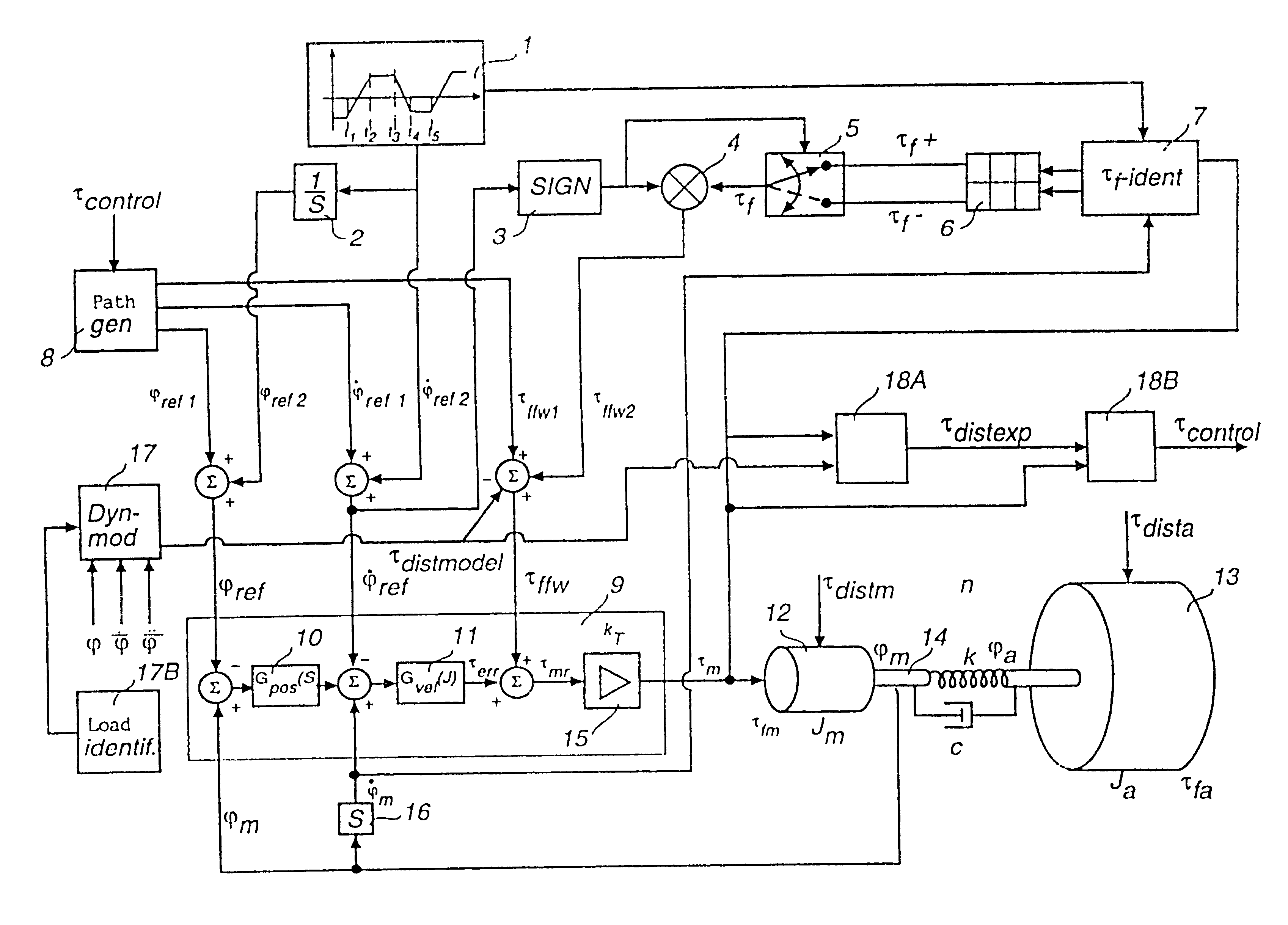
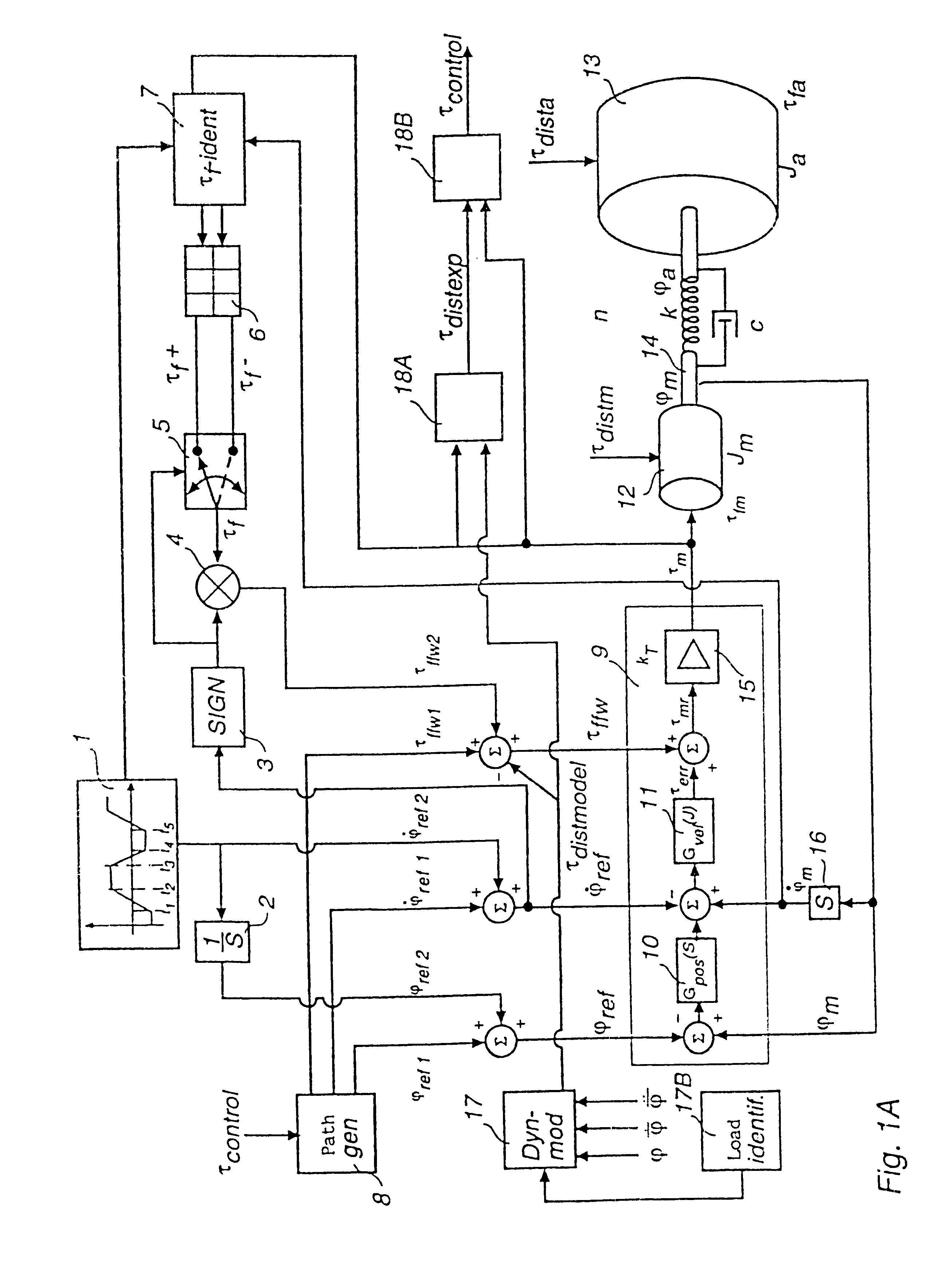
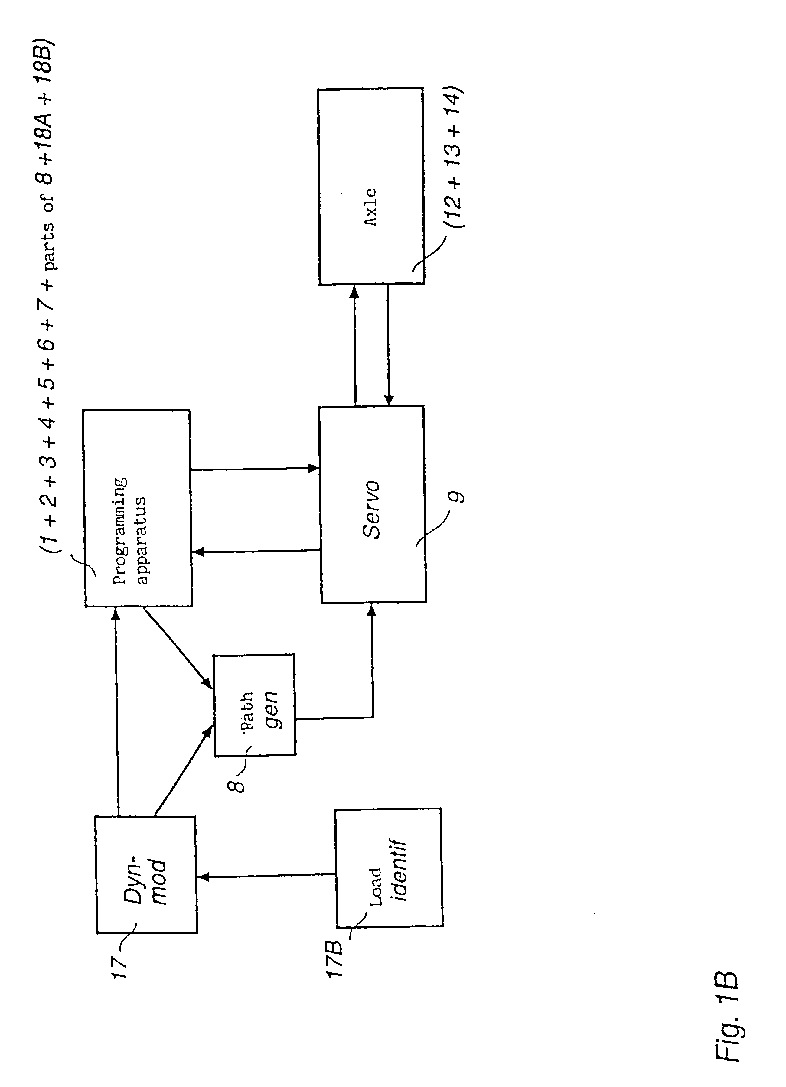
FIG. 1 shows for each of the axles of the robot a simple axle model 12, 13, 14, a cascade connected servo 9 and the circuits or reference generation to the servo during the programming phase 1, 8. The path generator 8 calculates position and speed references (.phi..sub.ref1,.phi..sub.ref1) and moment feed forward control signal (.tau..sub.ffw1) to the servo 9. The apparatus, integrated in the servo, for teach-in-programming and robot manipulation consists of the blocks 1, 2, 3, 4, 5, 6, 7 and 18 (A+B). In order to obtain a high sensitivity to external interference moments during the programming, a movement pattern from the function generator 1 is added to the servo references, which movement pattern is of such a nature that the arm will make small short movements to and fro during the programming. These movements make that static friction in motor, gearing and arm bearing is continuously overcome by the motor moment, which in its turn makes that external forces do not have to overco...


PUM


Abstract

An equipment for controlling an industrial robot, which robot has a plurality of rotation and / or translation axles (ax 1-6), comprising a motor (15) at each of said axles for generating desired movements of the arms and / or the wrist, of which the robot is constituted, a sensor at each of the axles for measuring axle angle and / or axle position, a servo (9) for each of the axles for controlling the motors based on measurement values from the sensors, and a path generator (8) for generating at least one reference (phiref, phiref, tauffw) for each of the servos (9). The equipment comprises an apparatus (1+2+3+4+5+6+7+parts of 8+18A+18B) at least one of the axles, which apparatus comprises a first device (18A) for calculation of the expected interference moment value (taudistexp) of said axle when the movable parts of the robot is not exposed to any external forces by interaction with the operator (64) or other things in the surroundings of the robot, and a second device (18B) for comparing this expected interference moment value (taudistexp) with values of the moment reference (taumr) of the servo (9) and / or with values of the moment (taum) of the motor and / or with values of the moment of the axle (14) and for forming, based on this comparison, a signal (taucontrol) for controlling the path generator (8). A method for programming / adjusting the movement of a robot is also included.

Description

This invention relates to an equipment for controlling an industrial robot. Furthermore, the invention relates to a method for programming and / or adjusting the movement of a robot.PRIOR ARTAn industrial robot comprises several arms, which are moveable in relation to each other, and a holder designed for mounting of the tool, object or gripping appliance, which the robot is to handle. The industrial robot is provided with a control system, which controls position and orientation of the tool / object / gripping appliance, and for each of the movement axles of the robot there is a servo system with a driving motor. The servo system of each axle is supplied with a reference value (desired valued) for the rotation angle of the axle and the driving motor of the axle makes the manipulator move in the axle in question until the axle position corresponds with the reference value supplied to the servo system. With an axle is here meant axle transmissions, which can cause rotation as well as trans...

Claims


Application Information

Patent Timeline
IPC IPC(8): G05B19/423B25J9/10B25J9/18B25J9/22G05B19/42G05D3/12
CPCG05B19/423
Inventor RAMSTROM, KARL-GUSTAVBROG.ANG.RDH, TORGNY
Owner ABB (SCHWEIZ) AG
Learn More