Magnetic field sensor having deformable conductor loop segment
Inactive Publication Date: 2002-11-26
ROBERT BOSCH GMBH
View PDF4 Cites 22 Cited by
Summary
Abstract
Description
Claims
Application Information
AI Technical Summary
This helps you quickly interpret patents by identifying the three key elements:
Problems solved by technology
Method used
Benefits of technology
Benefits of technology
According to a preferred development, in the undeformed state the conductor loop encloses an area having two longitudinal sides substantially parallel to one another, and the deformation device deforms the two longitudinal sides to change the enclosed area. It is thus advantageously possible to achieve a large change in area.
According to a further preferred development, the deformation device is configured such that it excites the two longitudinal sides to opposite-direction resonant flexural oscillations. It is thus advantageously possible to achieve a particularly large change in area utilizing resonance exaggeration.
According to a further preferred development, the conductor loop is configured such that the opposite-direction resonant flexural oscillations have a different resonant frequency from the corresponding same-direction resonant flexural oscillations. It is thereby advantageously possible to avoid interferences with the undesired same-direction resonant flexural oscillations, in which the net change in area is substantially zero.
According to a further preferred development, the conductor loop has a continuous, nondeformable first widthwise side having a greater thickness than the longitudinal sides, which is connected, via at least one deformable floating strut having substantially the thickness of the longitudinal sides, to at least one connector pad anchored in the substrate. This rigid first widthwise side stabilizes the width of the surface.
According to a further preferred development, the conductor loop has a split nondeformable second widthwise side having a greater thickness than the longitudinal sides, whose parts is connected via a respective deformnable floating strut, having substantially the thickness of the longitudinal sides, to a respective connector pad anchored in the substrate. This split rigid second widthwise side also stabilizes the width of the surface, and allows the induced voltage to be picked off advantageously.
According to a further preferred development, the longitudinal sides are connected at their first end, via a deformable floating first resilient strut having substantially the thickness of the longitudinal sides, to a connector pad anchored in the substrate. With this embodiment, the split rigid second widthwise side is advantageously omitted, so that the structure becomes simpler.
Problems solved by technology
Disadvantages that have emerged with the aforesaid known approaches are that they cannot withstand the severe mechanical and / or thermal stresses, and / or have too little sensitivity, and / or are very costly.
Method used
Image
Click on the blue label to locate the original text in one second.
Reading with bidirectional positioning of images and text.
Examples
first embodiment
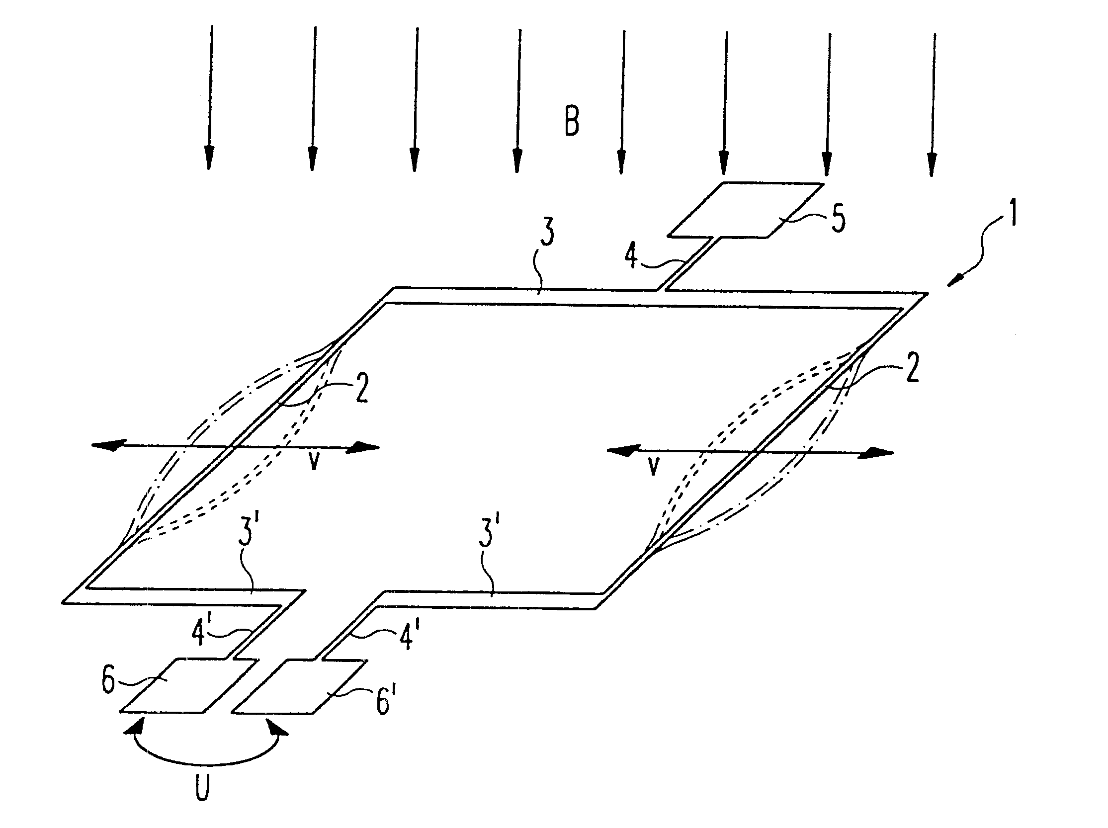
This first embodiment, like all the other embodiments described here, is manufactured using the technology of surface micromechanics, specifically with a silicon substrate.
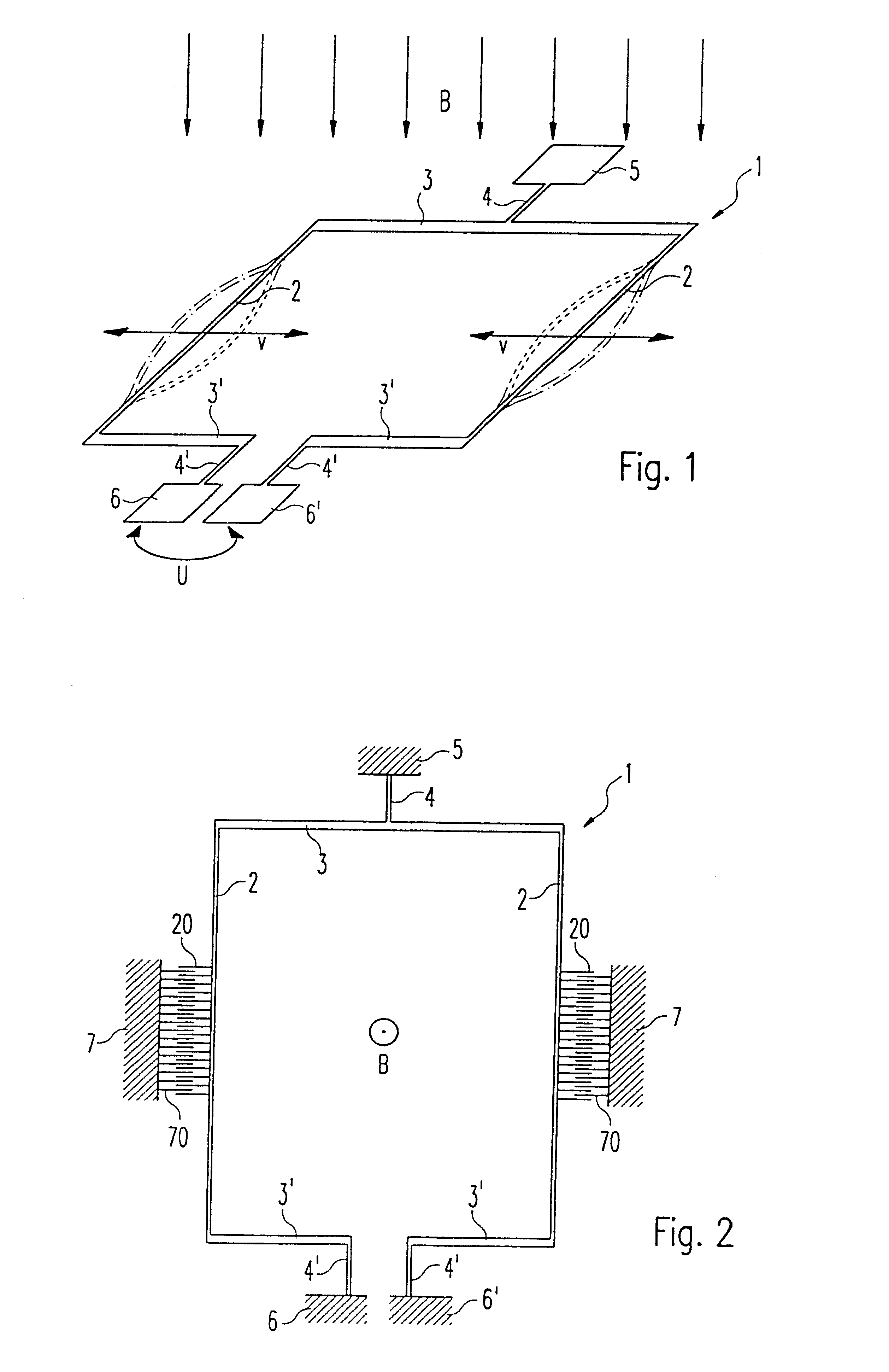
Conductor loop 1, which is substantially rectangular in shape, has its longitudinal sides 2 as thin bars, and its widthwise sides 3, 3' as thicker bars, arranged floatingly over the substrate. The continuous, thick (i.e. nondeformable) first widthwise side 3 is connected via the thin (i.e. deformable) floatinq strut 4 to connector pad 5 anchored in the substrate. The split, thick (i.e. nondeformable) second widthwise side 3' is connected via a respective thin (i.e. deformable) floating strut 4' to the respective corresponding connector pad 6, 6' anchored in the substrate.
Comb devices 20, 70 are also provided floatingly above the substrate, anchoring element 7 being anchored in the substrate.
The resilient attachment of conductor loop 1 to the substrate by way of the thin struts 4, 4' makes it possible to achieve a ...
second embodiment
The second embodiment is otherwise identical in function and configuration to the first embodiment.
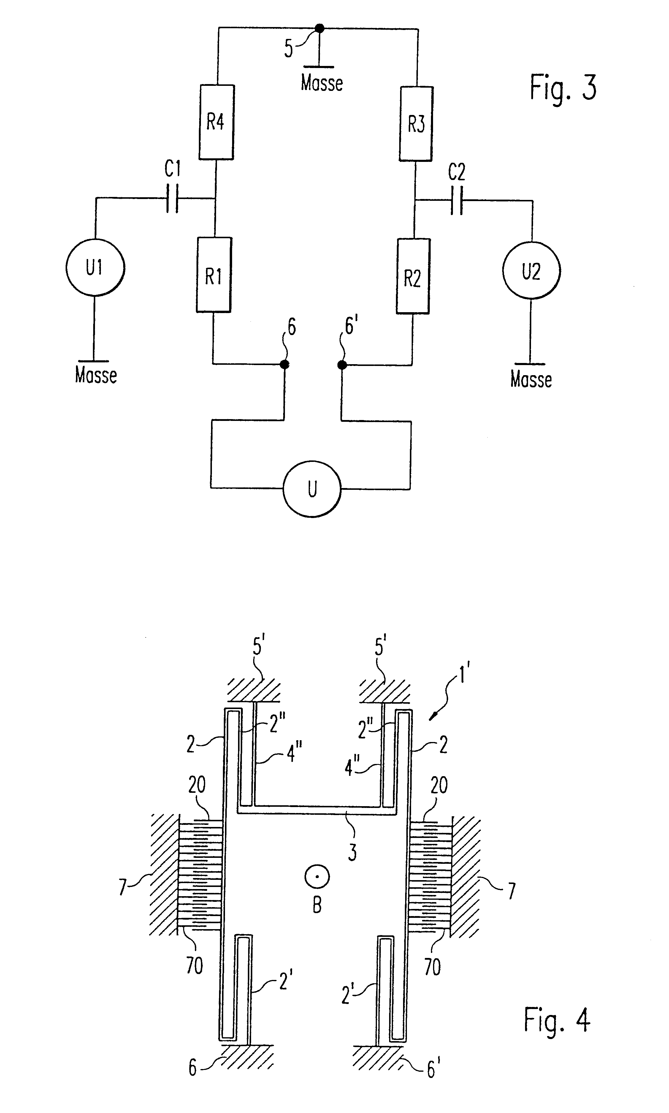
FIG. 5 is a schematic depiction of a third embodiment of the magnetic field sensor according to the present invention.
In FIG. 5, in addition to the reference characters already introduced, 1"' designates the conductor loop according to the third embodiment, 2"' a respective thin (i.e. deformable) resilient strut, and 8 an additional mass integrated into the longitudinal sides.
In contrast to the aforementioned first and second embodiments, in the third embodiment there is provided, floatingly above the substrate in the middle of deformable longitudinal sides 2, additional mass 8 by way of which the resonant frequency of longitudinal sides 2 can be tuned. Comb structure 80 is also provided on additional mass 8 instead of comb structure 20.
In addition, the attachment of longitudinal sides 2 at their upper edge to rigid widthwise side 3 is accomplished via the odified resilient struts 2"'....
third embodiment
The third embodiment is otherwise identical in function and configuration to the second embodiment.
PUM
Abstract
A magnetic field sensor that can be manufactured using the technology of surface micromechanics, having a conductor loop that has at least one deformable segment; a deformation device for deforming the deformable segment of the conductor loop with a predeterminable time dependence; a voltage sensing device for sensing the voltage induced at the ends of the conductor loop upon deformation in the presence of a magnetic field; and a magnetic field determining device for determining the present static and / or dynamic magnetic field in consideration of at least the time dependence of the deformation.
Description
The present invention concerns a magnetic field sensor, and in particular a magnetic field sensor that can be manufactured using the technology of surface micromechanics.BACKGROUND INFORMATIONAlthough applicable to any magnetic field sensor, the present invention and the problem on which it is based are explained with reference to a magnetic field sensor that can be manufactured using the technology surface micromechanics, for use in automotive engineering.Magnetic field sensors can be used in many ways in automotive engineering, for example in antilock braking systems (ABS) or in automatic slip control (ASR) systems as wheel sensors, as position sensors for needle valves or ignition pulse generators, as steering wheel angle transducers, as crankshaft position transducers, etc. The demands placed on these magnetic field sensors in terms of mechanical strength, e.g. shock resistance and temperature resistance, are usually very high.There exist in the related art a large number of kno...
Claims
Application Information
Patent Timeline
Application Date:The date an application was filed.
Publication Date:The date a patent or application was officially published.
First Publication Date:The earliest publication date of a patent with the same application number.
Issue Date:Publication date of the patent grant document.
PCT Entry Date:The Entry date of PCT National Phase.
Estimated Expiry Date:The statutory expiry date of a patent right according to the Patent Law, and it is the longest term of protection that the patent right can achieve without the termination of the patent right due to other reasons(Term extension factor has been taken into account ).
Invalid Date:Actual expiry date is based on effective date or publication date of legal transaction data of invalid patent.

